Gear case fault detection method combining vibration and sound wave monitoring

A fault detection and gearbox technology, applied in the field of detection, can solve the problems of inaccurate signals, complex vibration signals, low signal-to-noise ratio, etc., and achieve the effect of accurate data and reasonable operation

Inactive Publication Date: 2016-11-16
THE UNIV OF NOTTINGHAM NINGBO CHINA
View PDF12 Cites 16 Cited by
  • Summary
  • Abstract
  • Description
  • Claims
  • Application Information

AI Technical Summary

Problems solved by technology

[0005] 1) Since the vibration signal measured in the actual state is very complex, it generally includes the meshing vibration between gears, the rotational vibration of the camshaft, the resonance of the gearbox box, etc.; at the same time, the signal sampled on site also includes A large amount of measurement noise, the signal collected by the sensor is often a mixed signal generated by different signal sources, so the signal-to-noise ratio is low, which greatly affects the accuracy of the vibration signal characteristics for the diagnostic method;
[0006] 2) In addition, the sensor is installed on the gearbox. When the gears and shafts in the gearbox are running, a large amount of heat will be generated, which will gradually increase the temperature of the air in the gearbox, thereby making the environment around the sensor The temperature is abnormal, and the electronic components such as the sensor are greatly affected by the temperature, so the signal collected by the sensor will be inaccurate, which will affect the accuracy of fault detection and even cause damage to the sensor

Method used


Image

  • Gear case fault detection method combining vibration and sound wave monitoring
  • Gear case fault detection method combining vibration and sound wave monitoring

Examples


Embodiment Construction

[0023] The present invention will be described in further detail below in conjunction with the accompanying drawings and specific embodiments.

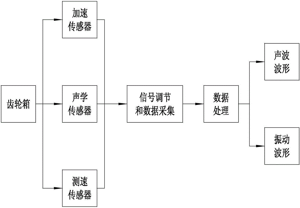
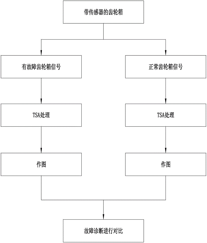
[0024] Depend on figure 1 and figure 2 As can be seen from the flow diagram in the gearbox fault detection method of the present invention combined with vibration and sound wave monitoring, it includes a vibration signal fault detection system and an acoustic signal fault detection system, and the signal generators of the two systems are all installed on the gear case; The specific steps of the gearbox fault detection method are as follows:

[0025] 1) The acceleration sensor in the vibration signal fault detection system is adsorbed on the gearbox casing, the acoustic sensor in the sound wave signal fault detection system is installed outside the gearbox, and the speed sensor is installed on the gear shaft;

[0026] 2) Set signal conditioning and data acquisition equipment outside the gearbox, and electrically connect the accelera...


PUM


Abstract

The invention discloses a gear case fault detection method combining vibration and sound wave monitoring. The method is achieved by a vibration signal fault detection system and a sound wave signal fault detection system. The method comprises steps of 1, adhering an accelerometer on the casing of a gear case, installing an acoustic sensor outside the gear case, and installing a speed measurement sensor on a gear rotary shaft; 2, arranging a signal adjusting and data collecting device outside the gear case; 3, processing data collected in the step 2 by a data processor to obtain a vibration waveform and an acoustic waveform; and 4, comparing the vibration waveform obtained after data processing with a normal vibration waveform of the gear case, supplementing comparison data of the vibration waveform by comparison data of the acoustic waveform, and performing final determination. Accordingly, by means of superposition of the vibration signal fault detection system and the sound wave signal fault detection system, the final detected data are enabled to be more accurate, and failure factors of the gear case can be well mastered.

Description

technical field [0001] The invention relates to the detection field, in particular to a gear box fault detection method combined with vibration and sound wave monitoring. Background technique [0002] Due to its fixed transmission ratio, large transmission torque and compact structure, the gearbox has been widely used in various machinery and equipment, and has become a variable speed transmission component of various machines. Especially in wind turbines, the gearbox can affect the effective utilization of the entire energy. Once the gearbox fails, it will stop the operation of the entire wind turbine. According to statistics, among the failure parts of the gearbox, the failure proportion of the gear itself is the largest, accounting for about 60%. It can be seen that the gear transmission is an important part that induces machine failure. Therefore, it is of great significance to carry out gearbox fault diagnosis. [0003] Fault diagnosis research on gearboxes has been g...

Claims


Application Information

Patent Timeline
Patent Type & Authority Applications(China)
IPC IPC(8): G01M13/02
CPCG01M13/021G01M13/028
Inventor 杜南丹尼斯·哈托诺
Owner THE UNIV OF NOTTINGHAM NINGBO CHINA
Why Eureka
Try Eureka