

Optical cavity, aerosol extinction instrument provided with optical cavity and aerosol extinction coefficient measurement method
An aerosol and extinction instrument technology, applied in the direction of color/spectral characteristic measurement, measuring devices, instruments, etc., can solve the problem of inaccurate real-time monitoring of aerosol extinction coefficient, and achieve compact instruments, high time resolution, and integration high effect
Inactive Publication Date: 2016-11-16
HEFEI INSTITUTES OF PHYSICAL SCIENCE - CHINESE ACAD OF SCI
View PDF6 Cites 6 Cited by
- Summary
- Abstract
- Description
- Claims
- Application Information
AI Technical Summary
Problems solved by technology
[0006] The object of the present invention is to provide an optical cavity, an aerosol extinction meter with the optical cavity and a method for measuring the aerosol extinction
Method used
View moreImage
Smart ImageViewing Examples

Examples
 PUM
 Abstract
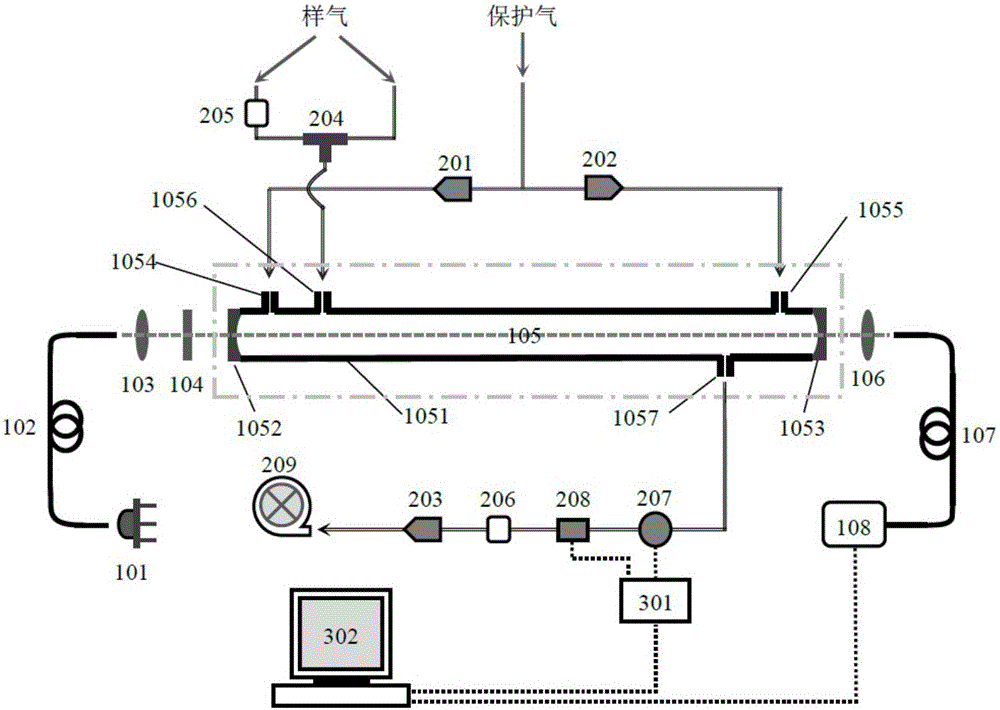
The invention discloses an optical cavity, which comprises a cavity body, the cavity body is in the shape of a cylinder, both ends of the cavity body are sealed with high-reflection cavity mirrors, and one side of the high-reflection cavity mirror is a curved surface. The high reverse surface, and the high reverse surfaces are all facing the cavity, and the reflectivity of the high negative surface is greater than 99.95%; the cavity is connected with the first protective gas nozzle, the second protective gas nozzle, the sampling gas nozzle and the exhaust gas The first protective gas nozzle and the second protective gas nozzle are separated at both ends of the cavity, the sampling gas nozzle and the exhaust nozzle are also separated at both ends of the cavity, and the first protective gas nozzle The gas nozzle and the second protective gas nozzle are relatively closer to the two ends of the cavity. Simultaneously, the invention also discloses a wide-band cavity-enhanced aerosol extinction instrument with the optical cavity, and a measurement method of the aerosol extinction spectrum realized by the aerosol extinction instrument. The measurement result of the invention has high accuracy.
Description
technical field [0001] The invention relates to the technical field of atmospheric aerosol extinction coefficient measurement, in particular to a broadband optical cavity, a broadband cavity enhanced aerosol extinction instrument with the optical cavity, and a method for measuring the aerosol extinction coefficient realized by using the aerosol extinction instrument. Background technique [0002] Atmospheric aerosol particles have an important impact on climate change, atmospheric environment and human health. Among them, the absorption and scattering of solar radiation by aerosol directly affects the earth's radiation balance and thus affects climate change. This absorption and scattering are collectively called extinction. Aerosol extinction also directly affects the visibility of the atmospheric environment. However, the spatiotemporal diversity of aerosol sources, scales, concentrations, and chemical components leads to spatiotemporal differences in aerosol optical prop...
Claims
Login to View More Application Information
Patent Timeline
 IPC IPC(8): G01N21/03G01N21/25G01N21/01
CPCG01N21/0303G01N21/01G01N21/25G01N21/255G01N2021/0112G01N2201/06
Inventor方波赵卫雄张为俊
OwnerHEFEI INSTITUTES OF PHYSICAL SCIENCE - CHINESE ACAD OF SCI