A mems substrate, a display unit comprising a mems substrate, and an intelligent display mirror

A display unit and substrate technology, applied in optical components, instruments, optics, etc., can solve the problems of high cost, small operating temperature range, thick panel, etc., and achieve the effect of cost reduction and simplified structure

Active Publication Date: 2019-05-07
TCL CHINA STAR OPTOELECTRONICS TECH CO LTD
View PDF6 Cites 0 Cited by
  • Summary
  • Abstract
  • Description
  • Claims
  • Application Information

AI Technical Summary

Problems solved by technology

The traditional smart display mirror is mainly based on liquid crystal display technology. The disadvantages of liquid crystal display are that the panel is thicker, the cost is higher, and the operating temperature range is smaller.

Method used


Image

  • A mems substrate, a display unit comprising a mems substrate, and an intelligent display mirror
  • A mems substrate, a display unit comprising a mems substrate, and an intelligent display mirror
  • A mems substrate, a display unit comprising a mems substrate, and an intelligent display mirror

Examples


Embodiment 1

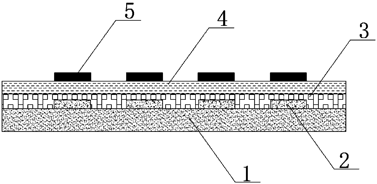
[0028] Embodiment 1: In this embodiment, the adjusting grating is made of a black light-absorbing material, which has better light-absorbing properties, so in this embodiment, the adjusting grating is called a light-absorbing grating. Such as figure 1 As shown, the MEMS substrate includes an array substrate 1, a reflective ambient light grating 2, an insulating layer 3, a color filter photoresist 4, and a light absorption grating 5. The reflective ambient light grating 2 is arranged on the array substrate 1, and the array substrate 1 provides reflective ambient light. The grating driving circuit of the grating 2 and the light-absorbing grating 5, the light-absorbing grating 5 is located above the reflective ambient light grating 2 and has a gap with the reflective ambient light grating 2, and the color film photoresist 4 is sandwiched between the reflective ambient light grating 2 and the light-absorbing grating 5 to make the MEMS substrate display a color screen.

[0029] Wh...

Embodiment 2

[0041] Embodiment 2: In this embodiment, the adjusting grating is made of highly reflective material, which has better reflected light characteristics. Therefore, in this embodiment, the adjusting grating is called a high reflective grating.

[0042] Figure 5 It is a structural diagram of a MEMS substrate containing a highly reflective grating, including an array substrate 1, a reflective ambient light grating 2, a color filter photoresist 4, and a high reflective grating 9. The reflective ambient light grating 2 is mounted on the array substrate 1, and the array substrate 1 provides reflection The grating driving circuit of the ambient light grating 2 and the highly reflective grating 9, the high reflective grating 9 is located above the reflective ambient light grating 2 and has a gap with the reflective ambient light grating 2, and the color film photoresist 4 is sandwiched between the reflective ambient light grating 2 and the gap between the high reflection grating 9 to ...


PUM


Abstract

The application provides an MEMS substrate, a display unit containing the same and an intelligent display mirror. The MEMS substrate provided by the present invention is characterized by orderly comprising an array substrate, a raster for reflecting ambient light, an insulating layer, a color film photoresistor and an adjusting raster, wherein the adjusting raster can move, the array substrate is equipped with an MEMS raster drive circuit, and the overlapping area of the adjusting raster and the raster for reflecting ambient light is adjusted and controlled by the drive circuit, thereby realizing a function of MEMS reflective display. The display unit provided by the present invention comprises a packaging substrate packaged on the MEMS substrate, and a metal thin film which is coated on the lower end face of the packaging substrate and is used for reflecting the external ambient light. The display mirror provided by the present invention comprises a plurality of display units in array arrangement. According to the present invention, by utilizing an MEMS technology, the multifunctional application of the mirror and the reflective display is realized, the structure of the display mirror is simplified, and the thickness of the display mirror and the cost are reduced.

Description

technical field [0001] The invention relates to the field of display technology, in particular to a MEMS substrate, a display unit using the MEMS substrate and an intelligent display mirror. Background technique [0002] Mirrors are an indispensable element in people's daily life. In the future, the application of mirrors will be more subdivided and specialized. There will be tailor-made mirrors for every occasion, such as vanity mirrors, car rearview mirrors, and bathroom wall mirrors. Wait, with the development of the economy and the improvement of living standards, people's demand for mirrors is not only the essential function of light reflection, but also the combination of aesthetics and multi-functional applications, such as smart windows, smart cars Mirrors and more. The traditional smart display mirror is mainly based on liquid crystal display technology. The disadvantages of liquid crystal display are thick panels, high cost, and small operating temperature range. ...

Claims


Application Information

Patent Timeline
Patent Type & Authority Patents(China)
IPC IPC(8): G02B26/02
CPCG02B26/02
Inventor 徐向阳
Owner TCL CHINA STAR OPTOELECTRONICS TECH CO LTD
Why Eureka
Try Eureka