Method for determining direct current power grid voltage compensation device installation positions and capacities

A technology of voltage compensation and DC power grid, which is applied in the direction of DC network circuit devices, circuit devices, electrical components, etc., can solve problems that do not involve the configuration of voltage compensation devices, and achieve the effect of minimizing device capacity and reducing investment

Active Publication Date: 2016-11-16
XI AN JIAOTONG UNIV
View PDF2 Cites 0 Cited by
  • Summary
  • Abstract
  • Description
  • Claims
  • Application Information

AI Technical Summary

Problems solved by technology

However, the document [A method for compensating the voltage loss of the DC power grid, CN105305404A, Song Guobing, etc.] only proposes a method for compensating the voltage drop, and does not involve the configuration of the voltage compensation device

Method used


Image

  • Method for determining direct current power grid voltage compensation device installation positions and capacities
  • Method for determining direct current power grid voltage compensation device installation positions and capacities
  • Method for determining direct current power grid voltage compensation device installation positions and capacities

Examples


Embodiment Construction

[0033] The present invention will be described in detail below in conjunction with the accompanying drawings and embodiments.

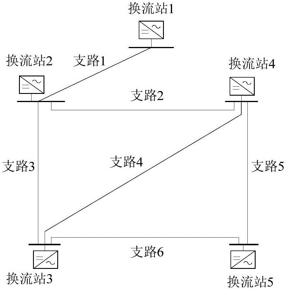
[0034] figure 1 Shown is a schematic diagram of a five-terminal DC power grid, which includes 5 nodes and 6 branches. The main parameters of the grid are shown in Table 1 and Table 2.

[0035] Table 1 Main parameters of DC power grid converter station

[0036]

[0037] Table 2 Main parameters of DC power grid lines

[0038]

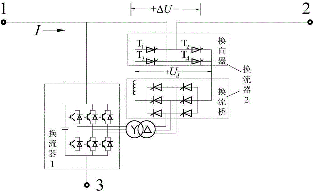
[0039] figure 2 Shown is an example of the structure of the voltage compensation device, which is a three-terminal structure, in which terminal 1 and terminal 2 are connected to the line, terminal 3 is grounded or connected to the terminal 3 of the opposite pole device, and there are two commutators inside the voltage compensation device Converter and an isolation transformer, in which converter 1 is connected between terminal 1 and terminal 3, converter 2 is connected between terminal 1 and terminal 2, the isolation t...


PUM


Abstract

The invention discloses a method for determining direct current power grid voltage compensation device installation positions and capacities. The method comprises the following steps: in a first step, in a preconceived working condition where network nodes are minimum in voltage, a power flow equation is established for power flow calculation, and nodes of which voltage values are lower than a lower operation limit Umin and are minimum is determined; in a second step, when voltage compensation devices are mounted in different branch circuits, sensitivity of the voltage values of the nodes with minimum voltages to control parameters of the voltage compensation device is solved; in a third step, according to the sensitivity and rated currents of the circuits, a precedence order for installing the compensation devices in the branch circuits is determined; in a fourth step, with an aim of minimizing voltage compensation device capacities, an optimization problem is constructed and solved while node voltages and parameters of the voltage compensation devices should be within limits; in a fifth step, compensation devices are symmetrically arranged on each branch circuit corresponding to a solution of the fourth step while the devices on the same branch circuit are equal in capacity. The method can be used for reasonably determining installation positions of the direct current power grid voltage compensation devices, and therefore device capacities and investment can be minimized.

Description

technical field [0001] The invention belongs to the technical field of DC power grids, and in particular relates to a method for determining the installation position and capacity of a DC power grid voltage compensation device. Background technique [0002] DC power grid is an effective technical means to solve problems such as long-distance large-capacity power transmission and renewable energy grid integration, and has attracted extensive attention from scholars at home and abroad. [0003] Unlike the active power and voltage in the AC grid, which can be adjusted separately, the power flow distribution of the DC grid depends on the node voltage difference. The existence of line resistance has caused the voltage of some nodes in the network to be significantly lower than the rated value when the line is long and under heavy load. The operating characteristics of the DC power grid will bring a series of problems, such as: 1) It is not conducive to the formulation of the vol...

Claims


Application Information

Patent Timeline
IPC IPC(8): H02J1/00
CPCH02J1/00
Inventor 宋国兵黄兴华王婷顾垚彬黄炜褚旭
Owner XI AN JIAOTONG UNIV
Why Eureka
Try Eureka