Ripple wave removing circuit, ripple wave removing method and LED circuit employing same

A ripple elimination and circuit technology, applied in the field of power supply, can solve the problems of large DC ripple, high cost and unfavorable circuit integration, and achieve the effect of solving the AC ripple problem

Active Publication Date: 2016-11-16
JOULWATT TECH INC LTD
View PDF4 Cites 4 Cited by
  • Summary
  • Abstract
  • Description
  • Claims
  • Application Information

AI Technical Summary

Problems solved by technology

[0002] At present, the LED lamp load is generally driven by converting the AC input power into DC power through the LED drive circuit, such as figure 1 As shown, the LED drive circuit outputs DC with sinusoidal ripples, and C01 is the output capacitor. When it is necessary to reduce the ripple of the output signal of the LED drive circuit, C01 needs to be a large electrolytic capacitor, and the high cost is not conducive to circuit integration.
When the LED drive circuit has a power factor correction function, the ripple of the output DC will be larger

Method used


Image

  • Ripple wave removing circuit, ripple wave removing method and LED circuit employing same
  • Ripple wave removing circuit, ripple wave removing method and LED circuit employing same
  • Ripple wave removing circuit, ripple wave removing method and LED circuit employing same

Examples


Embodiment Construction

[0040] Some preferred embodiments of the present invention will be described in detail below with reference to the accompanying drawings, but the present invention is not limited thereto.

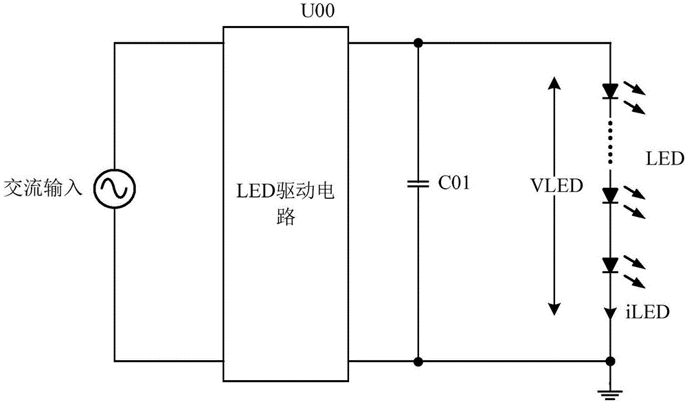
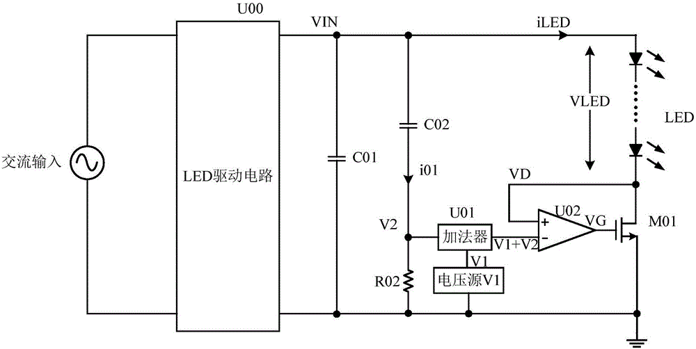
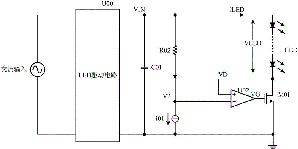
[0041] refer to figure 2 Shown is the circuit diagram of the LED circuit according to the first embodiment of the present invention, as figure 2 As shown, the LED circuit of the embodiment of the present invention includes an LED driving circuit U00, an output capacitor C01, an LED load and a ripple elimination circuit.

[0042] The LED drive circuit receives an external AC signal, and the output signal is filtered by the output capacitor C01 to generate a DC voltage signal with ripple, which is used as the input voltage signal VIN of the LED load.

[0043] In this embodiment, the ripple elimination circuit includes a first adjustment tube M01 connected in series with the load and a first adjustment tube control circuit, where the first adjustment tube M01 is connected between the load a...


PUM


Abstract

The invention discloses a ripple wave removing circuit, a ripple wave removing method and an LED circuit employing same. Power end voltage signals of an adjustment transistor which is connected with a load in series are controlled via an adjustment transistor control circuit, the power end voltage signals of the adjustment transistor are enabled to be voltage signals having ripple waves, and therefore input voltage signals input into an LED load can be direct current voltage signals without ripple waves, and therefore LED load flickering phenomena can be eliminated.

Description

technical field [0001] The invention relates to the field of power supplies, more specifically, to a ripple elimination circuit, a ripple elimination method and an LED circuit using the same. Background technique [0002] At present, the LED lamp load is generally driven by converting the AC input power into DC power through the LED drive circuit, such as figure 1 As shown, the LED drive circuit outputs DC with sinusoidal ripples, and C01 is the output capacitor. When it is necessary to reduce the ripple of the output signal of the LED drive circuit, C01 needs to be a large electrolytic capacitor, and the high cost is not conducive to circuit integration. When the LED drive circuit has a power factor correction function, the ripple of the output direct current will be larger. [0003] As we all know, the voltage and current of the LED lamp load are DC voltage and DC current with power frequency ripple. The ripple signal on the LED will cause the LED lamp to flicker, which w...

Claims


Application Information

Patent Timeline
Patent Type & Authority Applications(China)
IPC IPC(8): H05B33/08H05B44/00H05B45/12H05B45/36
CPCH05B45/44
Inventor 白浪黄必亮任远程周逊伟
Owner JOULWATT TECH INC LTD
Why Eureka
Try Eureka