LED (Light Emitting Diode) spotlight circuit compatible with electronic transformer

A technology for electronic transformers and LED spotlights, which is applied in the layout of electric lamp circuits, electric light sources, lighting devices, etc., can solve the problems of incompatibility with electronic transformers, and achieve the effect of saving installation and disassembly engineering costs, reasonable design and broad market prospects.

Active Publication Date: 2013-01-02
DONGGUAN KEETAT LIGHTING
View PDF4 Cites 2 Cited by
  • Summary
  • Abstract
  • Description
  • Claims
  • Application Information

AI Technical Summary

Problems solved by technology

[0003] The technical problem to be solved by the present invention is: to overcome the defect that the high-frequency electronic transformer driving circuit of the prior art cannot be compatible with the electronic transformer, to meet people's wishes and the market demand of LED spotlights, and to provide an LED that is compatible with the electronic transformer. Spotlight circuit, this kind of LED spotlight circuit compatible with electronic transformers is fully compatible with electronic transformers in the prior art. After the circuit of the present invention is installed in the LED spotlight, the LED spotlight will not be damaged during the lighting process. Flicker occurs, people can get the best lighting effect, and can achieve the purpose of energy saving

Method used


Image

  • LED (Light Emitting Diode) spotlight circuit compatible with electronic transformer
  • LED (Light Emitting Diode) spotlight circuit compatible with electronic transformer
  • LED (Light Emitting Diode) spotlight circuit compatible with electronic transformer

Examples


Embodiment 1

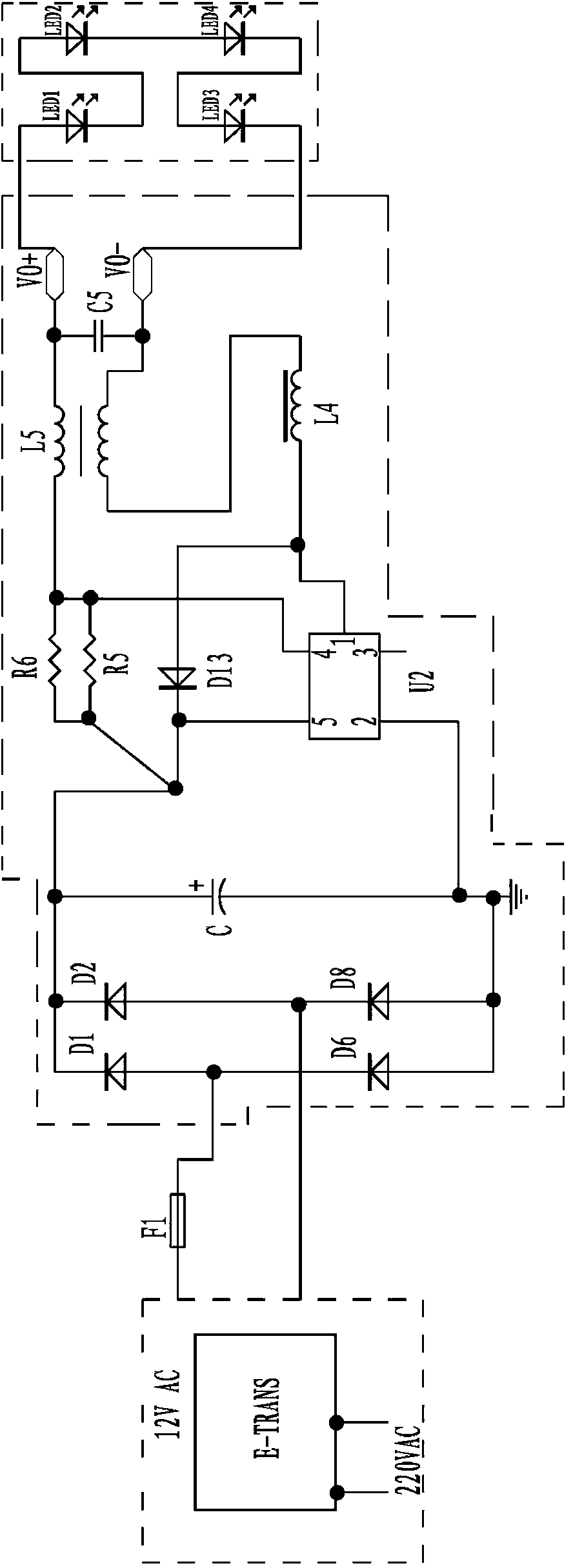
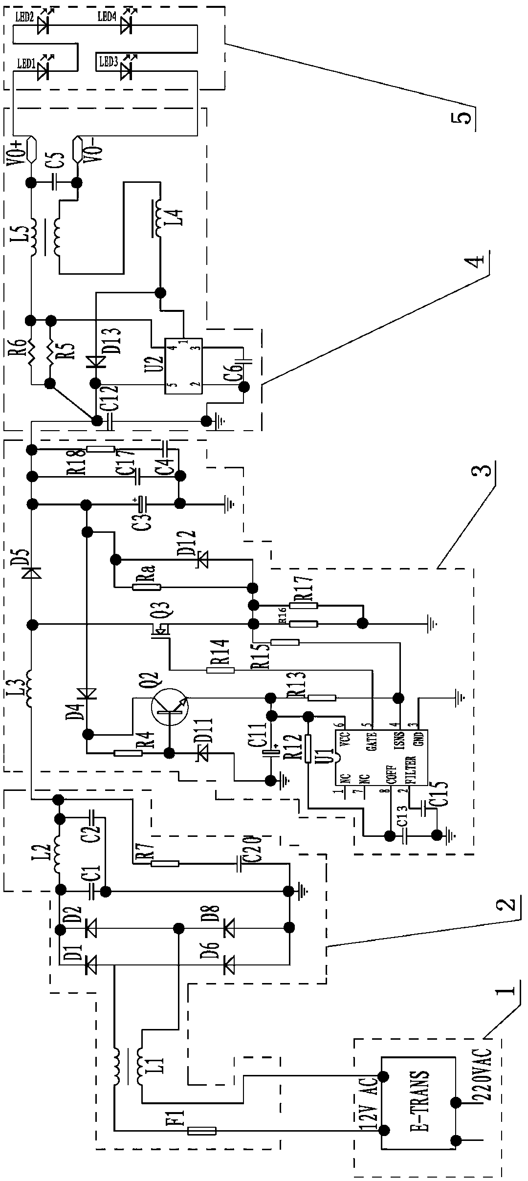
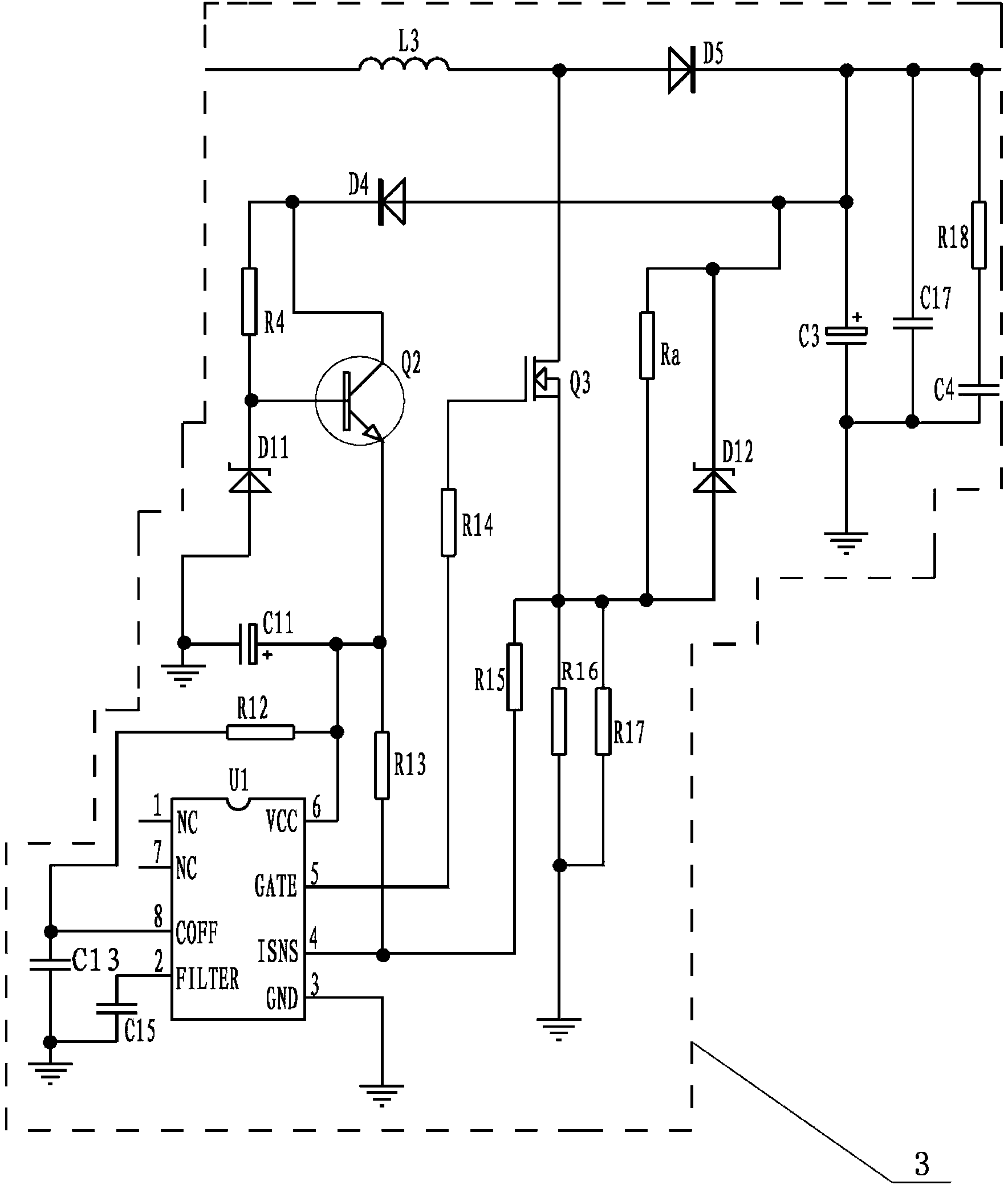
[0015] Embodiment one, such as figure 2 and image 3As shown, the electronic transformer-compatible LED spotlight circuit described in this embodiment includes a high-frequency electronic transformer circuit 1, a rectifier filter circuit 2, a step-down constant current circuit 4 and an LED module 5. The LED spotlight circuit of the transformer also includes a step-up circuit 3, and the high-frequency electronic transformer circuit 1, the rectification filter circuit 2, the step-up circuit 3, the step-down constant current circuit 4 and the LED module are sequentially connected; the step-up circuit 3 Including integrated circuit U1, electrolytic capacitor C11, transistor Q2, diode D4, diode D5, inductor L3, resistor R4, high-frequency switch tube Q3, bias resistor R13, resistor R14, resistor R16, resistor R17 and electrolytic capacitor C3; rectification The output end of the filter circuit 2 is connected to one end of the inductor L3, the anode of the diode D5 and the drain o...

Embodiment 2

[0016] Embodiment two, such as Figure 4 As shown, the electronic transformer-compatible LED spotlight circuit in this embodiment is different from that in Embodiment 1 in that the LED module 5 is connected in series with six strings of LEDs. Compared with Embodiment 1, this is more conducive to improving the light efficiency of the whole machine, making the energy-saving advantage of LED more obvious; the lighting effect is better, and the purpose of more energy saving can be achieved. Other structures and connection relationships of this embodiment, and the working principle of the booster circuit 3 are the same as those of Embodiment 1, and will not be repeated here.


PUM


Abstract

The invention relates to an LED (Light Emitting Diode) spotlight circuit compatible with an electronic transformer. The LED spotlight circuit comprises a high frequency electronic transformer circuit, a rectification and filter circuit, a voltage boost circuit, a voltage reduction and constant current circuit and an LED module, wherein the voltage boost circuit comprises an integrated circuit U1, an electrolytic capacitor C11, a triode Q2, a diode D4, a diode D5, an inductor L3, a resistor R4, a high frequency switching tube Q3, a biasing resistor R13, a resistor R14 and an electrolytic capacitor C3; the positive electrode of the diode D5 and the collector electrode of the high frequency switching tube Q3 are both connected with the other end of the inductor L3; the positive electrode of the diode D4 and the positive electrode of the electrolytic capacitor C3 are both connected with the negative electrode of the diode D5; one end of the resistor R4, the collector electrode of the triode Q2 are both connected with the negative electrode of the diode D4; and the positive electrode of the electrolytic capacitor C11, a 6th pin of the integrated circuit U1 and one end of the biasing resistor R13 are both connected with the emitter electrode of the triode Q2. The LED spotlight circuit provided by the invention is compatible with the electronic transformer.

Description

technical field [0001] The invention relates to the technical field of LED drive circuits, in particular to an LED spotlight circuit compatible with electronic transformers. Background technique [0002] With the development of semiconductor light-emitting technology, LEDs are also being used more and more widely because of their advantages such as energy saving and long life. LED has been widely used in different types of MR16 lamp cups because of its high lumen value and excellent light distribution performance. However, there is a common problem in the high-frequency electronic transformer drive circuit of the prior art, that is, the incompatibility of the electronic transformer. Most of the MR16 spotlights on the market now use a first-level BUCK topology circuit, such as figure 1 Shown: figure 1 It is a schematic diagram of an LED spotlight circuit in the prior art. Since the output of the electronic transformer is a high-frequency AC signal of about 12V, since this ...

Claims


Application Information

Patent Timeline
Patent Type & Authority Applications(China)
IPC IPC(8): H05B37/02
Inventor 安庆照
Owner DONGGUAN KEETAT LIGHTING
Why Eureka
Try Eureka