Board turnover mechanism

A technology of turning plate mechanism and bottom plate, applied in the direction of manipulator, secondary processing of printed circuit, electrical components, etc., can solve the problems of high labor intensity, affecting the quality of PCB board, low work efficiency, etc.

Active Publication Date: 2016-11-16
SUZHOU CONBER ELECTRONICS EQUIP
4 Cites 0 Cited by

AI-Extracted Technical Summary

Problems solved by technology

[0002] After the PCB board is soldered or printed, it is necessary to remove impurities such as stains and glue on the PCB board. At present, manual cleaning is generally used. After cleaning one side...

Method used

Two third guide rails 46 are installed on the preferred bearing 2 of the present invention, and the first stand 22, the second stand 24 are all installed on the two third guide rails 46, which is convenient to adjust the first stand 22 and ...

Abstract

The invention relates to a panel turnover mechanism, which comprises a support base and an elevating assembly for driving the support base to move up and down, wherein the support base is provided with a first motor and a cross rod; the cross rod is sleeved with a driving wheel and two first driven wheels; a first belt is connected between the first motor and the driving wheel; each first driven wheel is connected to a second driven wheel through a second belt; each second driven wheel is provided with a manipulator; the support base is provided with a first upright frame and a second upright frame separately; and two second driven wheels are arranged on the first upright frame and the second upright frame respectively. The board turnover mechanism is simple in structure, convenient to use and stable to clamp; a PCB is clamped through the manipulators; the support base and components on the support base are driven to ascend as a whole through cooperation of a second motor and a roller screw, so that a space is reserved for turnover of the PCB. The first motor is started and the manipulators are driven through the second driven wheels to rotate, so that the turnover of the PCB can be achieved; the turnover is reliable; and the work efficiency is high.

Application Domain

Gripping headsConductive pattern polishing/cleaning

Technology Topic

ManipulatorRoller screw +2

Image

  • Board turnover mechanism
  • Board turnover mechanism
  • Board turnover mechanism

Examples

  • Experimental program(1)

Example Embodiment

[0019] The present invention will now be further described in detail in conjunction with the accompanying drawings and embodiments. These drawings are all simplified schematic diagrams, only illustrating the basic structure of the present invention in a schematic manner, so it only shows the composition related to the present invention.
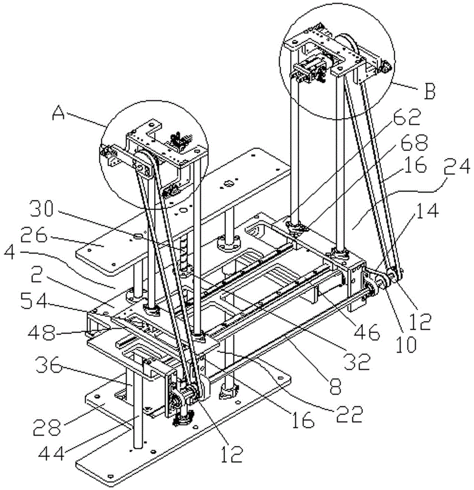
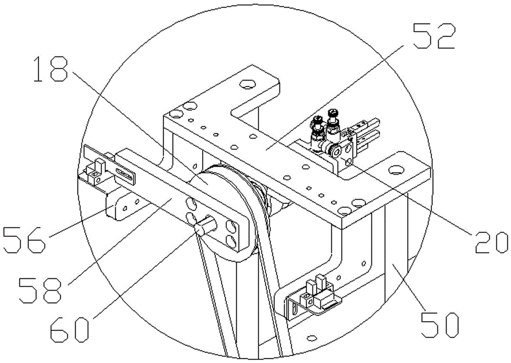
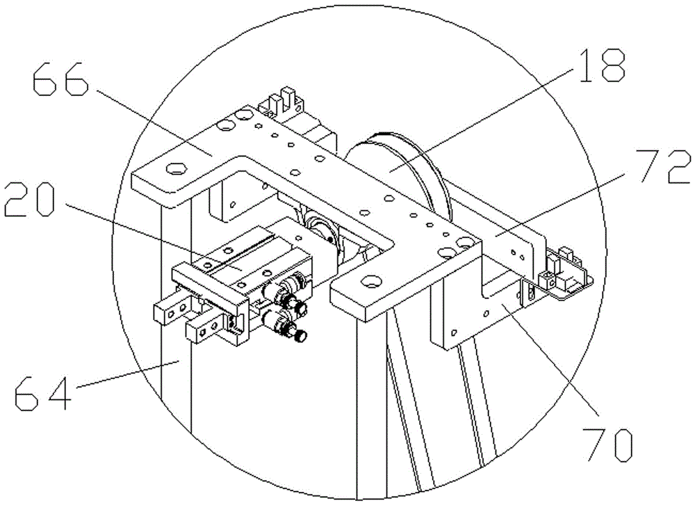
[0020] like Figure 1-Figure 6 As shown, a flap mechanism includes a support 2, a lifting assembly 4 that drives the support 2 to move up and down, a first motor 6, a cross bar 8 are installed on the support 2, and a drive wheel 10 is set on the cross bar 8. , two first driven pulleys 12, the first belt 14 is connected between the first motor 6 and the driving pulley 10, each first driven pulley 12 is connected with a second driven pulley 18 by a second belt 16, and the second driven pulley 18 is connected with the second driven pulley 18. The driving wheel 18 is equipped with a manipulator 20 , the support 2 is respectively equipped with a first stand 22 and a second stand 24 , and two second driven wheels 18 are installed on the first stand 22 and the second stand 24 respectively.
[0021] The preferred lifting assembly 4 of the present invention includes a first support plate 26 arranged up and down, a second support plate 28, a roller screw rod 30 installed between the first support plate 26 and the second support plate 28, and a roller screw rod 30 sleeved on the roller wire. The screw nut 32 on the rod 30 is connected with a driving mechanism 34 at one end of the roller screw rod 30 , and the screw nut 32 is fixed with the support 2 . When the driving mechanism 34 drives the roller screw 30 to rotate, the screw nut 32 moves up and down to drive the support 2 up and down. Further preferred driving mechanism 34 comprises second motor 36, the 3rd driven wheel 38 that is connected with second motor 36, the 4th driven wheel 42 that is connected with the 3rd driven wheel 38 by the 3rd belt 40, the 4th driven wheel 42 and roller Sub-screw mandrel 30 is fixed.
[0022] In order to realize the horizontal lifting of the support 2 and avoid deflection, the present invention also includes two guide rods 44, one end of each guide rod 44 is fixed to the first support plate 26, and the other end passes through the support 2 and the second support plate 28 fixed.
[0023] Two third guide rails 46 are installed on the preferred support 2 of the present invention, and the first stand 22 and the second stand 24 are all installed on the two third guide rails 46, which is convenient for adjusting the first stand 22 and the second stand 24, thereby adjusting the distance between the two manipulators 20, which is convenient for clamping PCB boards of different widths, has a wide range of applications, and reduces production costs.
[0024] The preferred first stand 22 of the present invention includes a first base plate 48, two first uprights 50 fixed on the upper end of the first base 48, a first support plate 52 fixed on the top of the two first uprights 50, and a first support plate fixed on the second Two first sliders 54 at the lower end of a bottom plate 48, a first shelf 56 is installed on the first support plate 52, a first bearing plate 58 is installed on the first shelf 56, the first bearing plate 58 and the second slave A first pivot 60 is disposed between the driving wheels 18 , and the second driven wheel 18 rotates around the first pivot 60 . The second stand 24 includes a second base plate 62, two second uprights 64 fixed on the upper end of the second base 62, a second support plate 66 fixed on the top of the two second uprights 64, and a second support plate fixed on the second base 62. Two second sliders 68 at the lower end, a second shelf 70 is installed on the second support plate 66, a second bearing plate 72 is installed on the second shelf 70, and the connection between the second bearing plate 72 and the second driven wheel 18 A second fulcrum (not shown in the figure) is arranged between them.
[0025] When the present invention is in use, both the first support plate 26 and the second support plate 28 are installed on a frame. When the PCB board on the conveying track needs to be turned over, the manipulator 20 clamps the PCB board, and the second motor 36 is started. Through the cooperation of the third driven wheel 38, the third belt 40 and the fourth driven wheel 42, the roller screw 30 is driven to rotate, and the screw nut 32 drives the support 2 and the components on the support 2 to rise as a whole, and the PCB board rises. Thereby providing space for the flipping of the PCB board, the first motor 6 starts, the driving wheel 10 rotates, the two first driven wheels 12 are driven to rotate by the cross bar 8, and the two second driven wheels 18 are driven by the two second belts 16, The second driven wheel 18 drives the manipulator 20 to rotate, drives the PCB board to turn over 180°, the support 2 descends under the drive of the screw nut 32, the PCB board falls on the conveying track, and the manipulator 20 releases the PCB board.
[0026] The above is inspired by the ideal embodiment of the present invention. Through the above description, relevant personnel can make various changes and modifications within the scope of not departing from the technical idea of ​​the present invention. The technical scope of the present invention is not limited to the content in the specification, and must be determined according to the scope of the claims.

PUM

no PUM

Description & Claims & Application Information

We can also present the details of the Description, Claims and Application information to help users get a comprehensive understanding of the technical details of the patent, such as background art, summary of invention, brief description of drawings, description of embodiments, and other original content. On the other hand, users can also determine the specific scope of protection of the technology through the list of claims; as well as understand the changes in the life cycle of the technology with the presentation of the patent timeline. Login to view more.
Why Eureka
Try Eureka