Spindle retainer for a readjustment device

A technology for maintaining devices and compensating adjustments, which is applied in friction clutches, clutches, mechanically driven clutches, etc., and can solve problems such as excessive load on shaft sleeves, fatigue cracks, etc.

Active Publication Date: 2016-11-16
SCHAEFFLER TECH AG & CO KG
View PDF3 Cites 2 Cited by
  • Summary
  • Abstract
  • Description
  • Claims
  • Application Information

AI Technical Summary

Problems solved by technology

However, it has been found that such bushings can be subjected to excessive loads during operation, in particular due to centrifugal forces, and can have fatigue cracks

Method used


Image

  • Spindle retainer for a readjustment device
  • Spindle retainer for a readjustment device
  • Spindle retainer for a readjustment device

Examples


Embodiment Construction

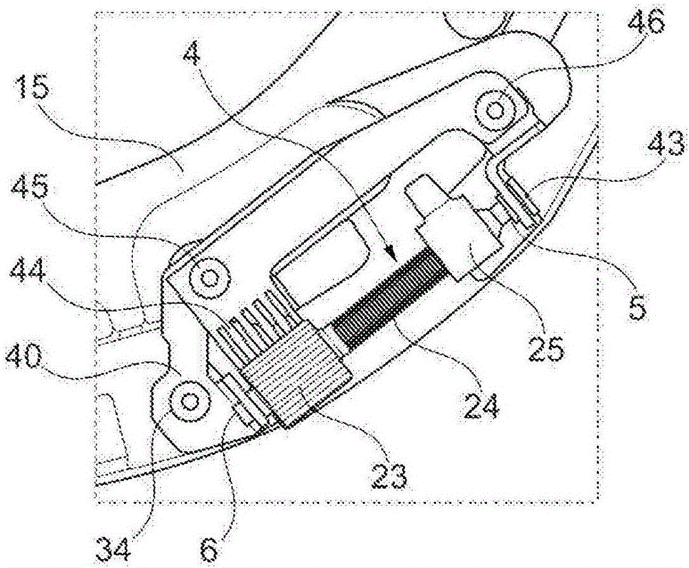
[0056] figure 1 A conventional receptacle 40 is shown in , which is fastened to an extruded plate 15 by means of a first fastening element 34 , a second fastening element 45 and a third fastening element 46 . The screw shaft 4 with the drive pinion 23 and the screw drive 24 is held with a first end 5 in a bushing 43 . In this view, locking pawls 44 can be seen which, via the drive pinion 23 , secure the position of the spindle nut 25 on the spindle drive 24 of the spindle 4 in an adjusted position.

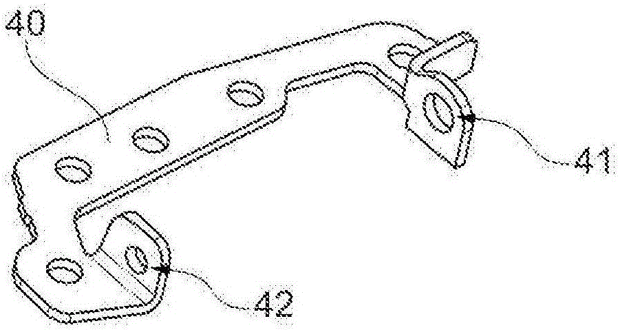
[0057] figure 2 shown in figure 1 A conventional receptacle 40 as in , wherein a first opening 41 and a conventional second opening 42 can be recognized here. It is clear that in this case the screw shaft 4 has to be pushed through the conventional first opening 41, wherein the drive pinion 23 and the screw nut 25 can then be inserted as figure 1 to the screw shaft 4 as shown in .

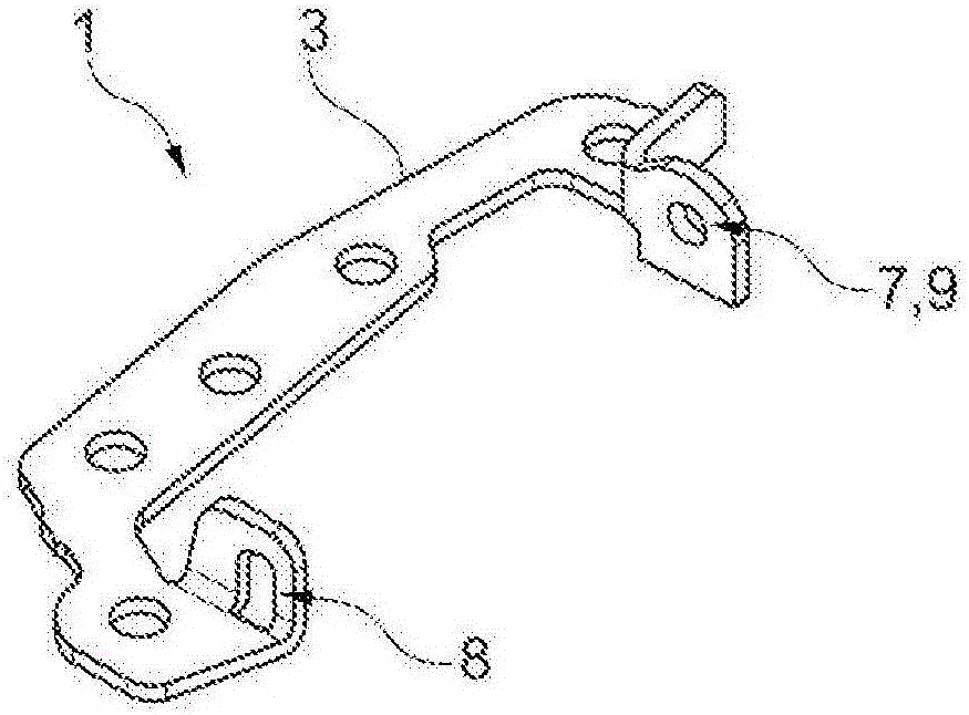
[0058] image 3 shows the receptacle 3 of the screw holding device 1 according to the invent...


PUM


Abstract

The invention relates to a spindle retainer for a readjustment device, which spindle retainer comprises at least the following components: a receptacle for a spindle shaft having a first end and a second end, wherein the receptacle has a first opening and a second opening, wherein the first opening forms an accurately fitting first supporting retainer for the first end of the spindle shaft and the second opening is designed in such a way that the second end of the spindle shaft can be pivoted into the second opening in order to be brought into a final mounting position; a blocking device, which has a third opening for the second end, wherein the third opening forms an accurately fitting second supporting retainer for the final mounting position of the spindle shaft, and wherein the blocking device can be fastened in relation to the receptacle; and a connecting surface, by means of which the spindle retainer can be connected to a component of a friction clutch, preferably to a pressure plate. The invention further relates to a method for mounting a spindle shaft in a spindle retainer according to the description above, which method comprises at least the following steps: a) inserting the spindle shaft into the first opening of the receptacle by means of the first end of the spindle shaft; b) pivoting the spindle shaft into the second opening of the receptacle by means of the second end of the spindle shaft; c) sliding the blocking device onto the second end of the spindle shaft by means of the third opening; and d) fastening the blocking device in relation to the receptacle, wherein the spindle shaft is axially and radially fastened in a final mounting position. By means of the spindle retainer according to the invention, simplified mounting of the readjustment device can be achieved.

Description

technical field [0001] The invention relates to a screw holding device for a compensating adjustment device and to a compensating adjustment device for a friction clutch, in particular for a motor vehicle. Background technique [0002] Compensating adjustment devices are known in the prior art, in which a screw shaft with a screw drive is used. In this case, the screw drive is driven by a drive pinion, and the screw nut is moved in translation by the screw drive. In this case, the screw shaft is supported radially at two points, wherein the screw shaft has to absorb several centrifugal forces simultaneously, and the compensation adjustment device is mounted on the rotating component of the friction clutch, preferably on the motor side. The platen is subjected to these centrifugal forces. Hitherto known are holding devices for screw shafts in which the screw shaft has to be guided through openings and at least one bushing has to be introduced into the shaft for fixing the s...

Claims


Application Information

Patent Timeline
Patent Type & Authority Applications(China)
IPC IPC(8): F16D13/75
CPCF16D13/757
Inventor L·福斯珀尔斯T·福雷尔T·默克林M·施奈德
Owner SCHAEFFLER TECH AG & CO KG
Why Eureka
Try Eureka