Compensation adjustment device for friction clutch

A friction clutch, compensation and adjustment technology, applied in the direction of friction clutch, clutch, mechanical drive clutch, etc.

Inactive Publication Date: 2017-01-18
SCHAEFFLER TECH AG & CO KG
View PDF5 Cites 0 Cited by
  • Summary
  • Abstract
  • Description
  • Claims
  • Application Information

AI Technical Summary

Problems solved by technology

A disadvantage of such a construction is that in particular worm drives and screw drives are subjected to high centrifugal forces which are directed transversely to the axial orientation of these devices

Method used


Image

  • Compensation adjustment device for friction clutch
  • Compensation adjustment device for friction clutch
  • Compensation adjustment device for friction clutch

Examples


Embodiment Construction

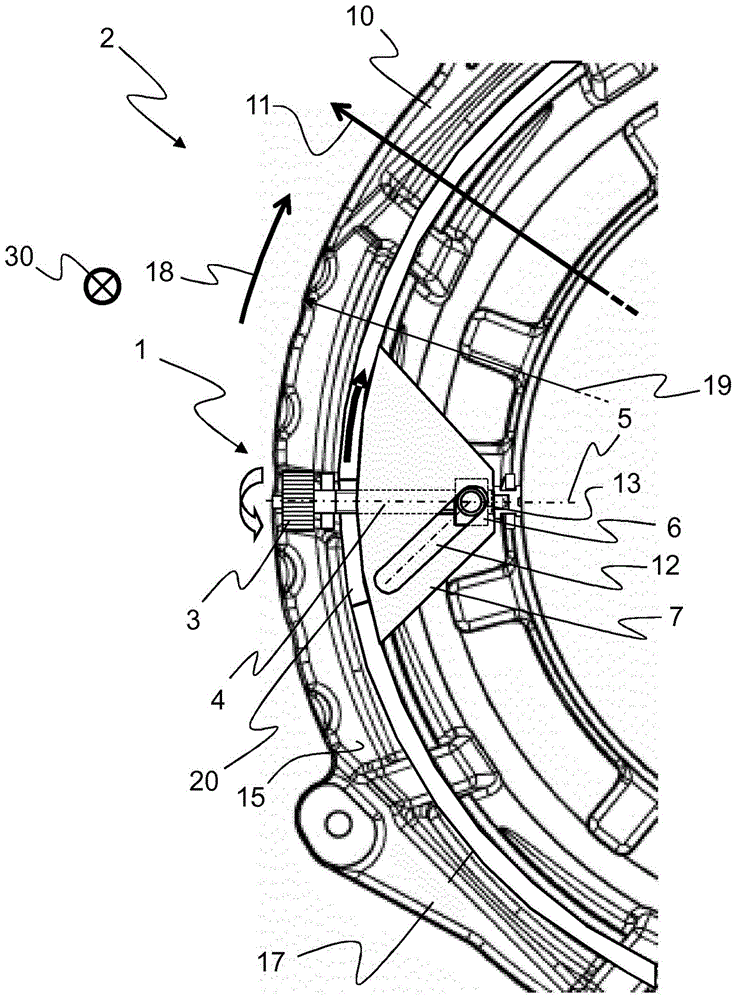
[0046] figure 1 The compensation adjustment device 1 is shown in a friction clutch 2 shown in part, the compensation adjustment device 1 being arranged on the rear side 15 of the pressure plate 10 . The axial direction 5 of the compensation adjusting spindle 4 is arranged parallel to the radial direction 11 of the friction clutch 2 . The rotatable drive 3 is arranged on the outer circumference 19 of the pressure plate 10 . The compensation adjustment screw 4 extends through a groove 20 in the ramp ring 17 . By twisting the drive 3 , the spindle nut 6 is moved on the compensating adjusting spindle 4 in the axial direction 5 outwards (indicated by the arrow pointing to the left in the figure). The slide 13 thus moves in the link 12 of the adjusting unit 7 in the axial direction 5 or in the radial direction 11 of the friction clutch 2 . The ramp ring 17 is thus moved in a circumferential direction 18 which is indicated by an arrow on the ramp ring 17 . The bevel 16 of the pre...


PUM


Abstract

The invention relates to a compensating adjustment device (1) for a friction clutch (2), comprising at least the following components: a torsionable drive (3); a compensating adjusting screw (4) with an axial direction, The compensation adjustment lead screw is connected to the driving device without relative rotation; the lead screw nut (6), which is moved along the axial direction by the twisting of the compensation adjustment lead screw; the adjustment unit (7 ), used to adjust the distance (8) between an engagement device (9) and a pressure plate (10), the adjustment unit is adjusted by the axial movement of the screw nut (6), so that the The axial direction (5) of the compensation adjusting spindle (4) can be oriented parallel to the radial direction (11) of the friction clutch (2). With the compensating adjustment device proposed here, it is possible to realize a durable functional unit which is designed to be sufficiently rigid with respect to the applied centrifugal forces with low manufacturing requirements and low weight and installation space.

Description

technical field [0001] The invention relates to a compensating adjustment device for a friction clutch, which is provided for compensating for an extension of the engagement displacement, for example in the case of a reduced friction lining thickness of the friction clutch. Such compensating adjustment devices or friction clutches can be used in particular when starting and disengaging a motor vehicle. Background technique [0002] In a friction clutch, a plurality of friction surfaces come into contact with each other to transmit torque, and relative motion occurs between these friction surfaces. Wear in the form of material loss necessarily occurs here, so that the distance between the two friction surfaces increases due to the reduction in the thickness of the friction lining due to the increased wear of the friction clutch. The joining elements must generate enormous forces, for which a complex structural design is required. It is advantageous here that despite variati...

Claims


Application Information

Patent Timeline
Patent Type & Authority Patents(China)
IPC IPC(8): F16D13/75
CPCF16D13/757F16D13/75F16D13/38
Inventor G·阿纳特
Owner SCHAEFFLER TECH AG & CO KG
Why Eureka
Try Eureka