Supercharge Your Innovation With Domain-Expert AI Agents!

Method and apparatus for tracking an uplink beam

一种链路、波束的技术,应用在跟踪上行链路波束领域,能够解决很长时间、通信中断等问题

Active Publication Date: 2020-07-14
SAMSUNG ELECTRONICS CO LTD
View PDF5 Cites 0 Cited by
  • Summary
  • Abstract
  • Description
  • Claims
  • Application Information

AI Technical Summary

Problems solved by technology

However, due to the physical constraint that the MS cannot measure the received signal quality of multiple beam pairs at once, it takes a long time to detect the best beam pair
When a handover event occurs as the MS moves from the serving cell to a neighboring cell, this time delay may cause a communication interruption while the MS is searching for a new beam pair for the neighboring cell

Method used


Image

  • Method and apparatus for tracking an uplink beam
  • Method and apparatus for tracking an uplink beam
  • Method and apparatus for tracking an uplink beam

Examples


Embodiment Construction

[0033]Preferred embodiments of the present disclosure will be described in detail with reference to the accompanying drawings. A detailed description of known functions or constructions will be omitted lest it would obscure the subject matter of the present disclosure. Terms used herein are defined in consideration of functions according to the present disclosure, and may be changed according to user's or operator's intention or custom. Therefore, definitions should be made based on the overall content of the present disclosure.

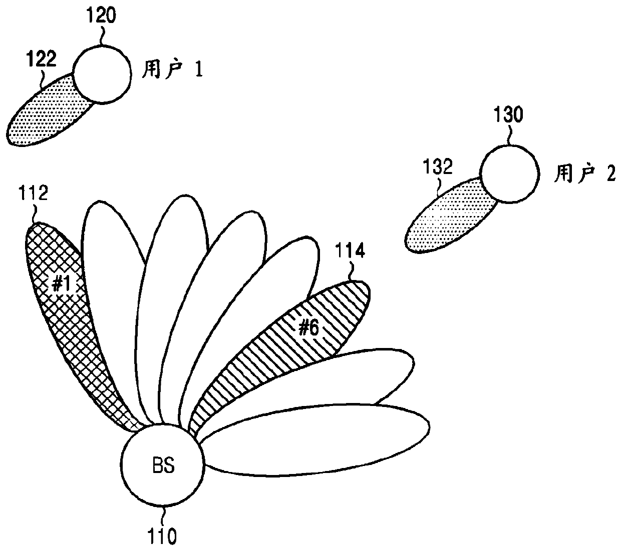
[0034] figure 1 An exemplary beamforming-based cellular system to which the present disclosure is applicable is illustrated.

[0035] refer to figure 1 , a base station (BS) 110 may serve mobile stations (MS) 120 and 130 within a cell using a transmit antenna configured as an array antenna. BS 110 forms beams for one or more scheduled MSs 120 and 130 by controlling gain values ​​for each transmit antenna direction (or channel). In the illustrate...


PUM


Abstract

Methods and apparatus for tracking uplink beams in a beamforming based cellular system are disclosed. A method for a terminal comprising the steps of: sending a measurement report including signal quality of the serving base station and neighboring base stations to a serving base station; receiving uplink beam tracking information of at least one beam tracking target base station from the serving base station; transmitting an uplink beam training signal for the beam tracking target base station based on the uplink beam tracking information; and receiving information from the serving base station on an optimal terminal transmission beam of the beam tracking target base station, and Store the received information.

Description

technical field [0001] The present disclosure relates to methods and apparatus for tracking uplink beams for efficient handover in beamforming based cellular systems. Background technique [0002] In order to meet the demand for wireless data services that have been increasing since the commercialization of the fourth generation (4G) communication system, efforts have been made to develop the fifth generation (5G) or quasi-5G communication system. This is why a 5G or quasi-5G communication system is called over a 4G network communication system or a post-Long Term Evolution (LTE) system. [0003] To achieve high data rates, it is worth considering deploying 5G communication systems in millimeter-wave (mmWave) frequency bands (eg, 60-GHz frequency band). In order to reduce the propagation path loss and increase the propagation distance in the mmWave frequency band, beamforming, massive multiple-input multiple-output (MIMO), omnidirectional MIMO (FD-MIMO), array antennas, ana...

Claims


Application Information

Patent Timeline
Patent Type & Authority Patents(China)
IPC IPC(8): H04W24/00H04W24/10
CPCH04W24/00H04W24/10H04B7/0404H04B7/0408H04B7/0695H04W36/08H04W36/38H04W36/00835H04W36/0085H04B7/0617H04L43/08H04W36/302H04W72/21
Inventor 柳铉逸
Owner SAMSUNG ELECTRONICS CO LTD
Features
  • R&D
  • Intellectual Property
  • Life Sciences
  • Materials
  • Tech Scout
  • Unparalleled Data Quality
  • Higher Quality Content
  • 60% Fewer Hallucinations
Learn More