Temperature adjustment method for inner-outer-wall-structured heat preservation device and heat preservation device implementing temperature adjustment method

A technology for temperature regulation and structural heat preservation, which is applied to drinking water vessels, heating devices, cooking vessels, etc. It can solve the problems of contact, sometimes disconnection, inconvenient carrying, affecting heat preservation and heat dissipation performance, etc., and achieves the effect of ease of use

Active Publication Date: 2016-11-23
车晋中
View PDF11 Cites 33 Cited by
  • Summary
  • Abstract
  • Description
  • Claims
  • Application Information

AI Technical Summary

Problems solved by technology

Chinese Invention Patent Publication (CN204520141U) discloses a method for realizing the heating and cooling function of a vacuum heat preservation appliance, but there are also the following disadvantages: because one end of the metal sheet is a free end, it can only be placed in a stationary and upright state (upright or upside down). )

Method used

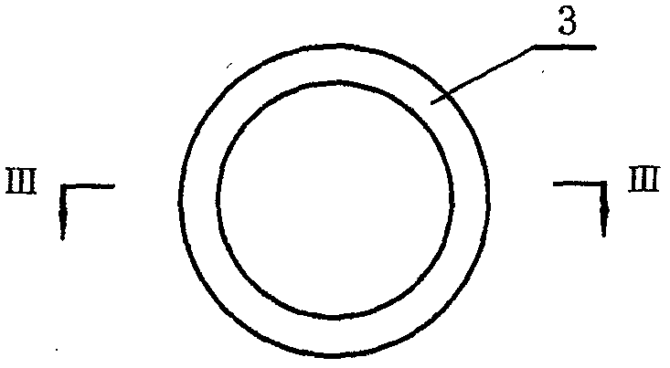
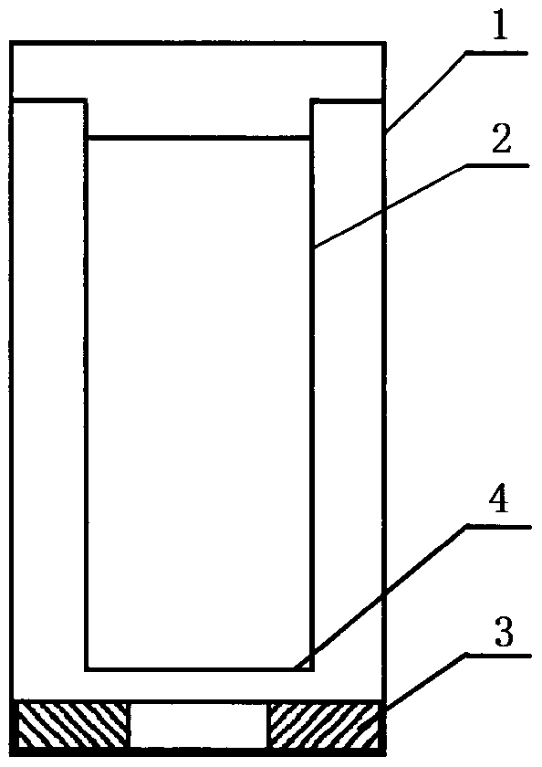
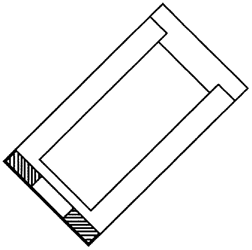

Image

  • Temperature adjustment method for inner-outer-wall-structured heat preservation device and heat preservation device implementing temperature adjustment method
  • Temperature adjustment method for inner-outer-wall-structured heat preservation device and heat preservation device implementing temperature adjustment method
  • Temperature adjustment method for inner-outer-wall-structured heat preservation device and heat preservation device implementing temperature adjustment method

Examples


Embodiment approach

[0114] In order to facilitate people to carry the heat preservation appliance of the present invention, a portable structure can be arranged on the upper and lower parts of the outer surface of the heat preservation appliance, so that people can lift the heat preservation appliance from two directions up and down, so that the heat preservation appliance can be easily heated in both the heat preservation and heat dissipation states. carry. The hand-carrying structure can be a quick buckle type, a quick hook type, an "I"-shaped cross-section handle type, a "T"-shaped cross-section handle type, and the like. Figure 24 It is an embodiment of the portable structure, including: "I"-shaped section handle 14, "C"-shaped movable buckle 15, hand strap 16, wherein "C"-shaped movable buckle 15 can be Slide up and down in the section handle 14 slots, and the hand strap 16 is connected with the "C" font movable buckle 15. During use, the "C" font movable buckle 15 can slide to the upper a...


PUM


Abstract

The invention provides a temperature adjustment method for an inner-outer-wall-structured heat preservation device and the heat preservation device implementing the temperature adjustment method, relating to a method for transferring heat between inner and outer walls in a sealing cavity of the heat preservation device and further relating to a multifunctional heat preservation device with heating and cooling functions. The heat preservation device comprises an outer wall (1), an inner wall (2), a controllable heat transfer medium (3), a heat transfer boss (4) and a limiting structure (7). Under a heat preservation state, the heat transfer medium (3) is only in contact with the outer wall (1) or the inner wall (2), and a thermal insulation state is formed between the inner and outer walls in the heat preservation device. Under a heat dissipation state, the heat transfer medium (3) is fit with the heat transfer boss (4) between the inner and outer walls of the heat preservation device, and heat is transferred through the inner wall (2), the heat transfer boss (4), the heat transfer medium (3) and the outer wall (1). Under the action of the limiting structure, the heat preservation device can be in a reliable heat preservation or heat dissipation state no matter when the heat preservation device is placed upwards, downwards, obliquely and transversely or when the people move. The heat preservation device provided by the invention has a reliable heat preservation function and is capable of heating and cooling under a sealing state, so that the pollution of liquid to air is avoided, and meanwhile, sprinkling and scalding are prevented; and the heat preservation device can be used as a warming device in cold winter.

Description

technical field [0001] The invention relates to a method for adjusting the temperature of a heat-preservation appliance with an inner and outer wall structure, including a heat transfer method between the inner and outer walls of the cavity of the heat-retention appliance. [0002] The invention also relates to a temperature-adjustable multifunctional thermal insulation appliance, which includes an outer wall, an inner wall, a heat transfer medium, and the like. It is characterized in that the heat-transfer medium between the inner and outer walls of the heat-preservation appliance is in a controlled state, so as to realize reliable heat preservation and heat dissipation. Background technique [0003] In real life, throughout the year, especially in the hot summer or cold winter, people are accustomed to using thermal insulation appliances to keep the temperature of objects, and the vacuum thermal insulation appliances with inner and outer wall structures have a better therm...

Claims


Application Information

Patent Timeline
IPC IPC(8): A47J36/24A47G19/22
CPCA47G19/22A47J36/24A47J36/2411
Inventor 车晋中
Owner 车晋中
Why Eureka
Try Eureka