Micro powder manufacturing equipment

A technology for manufacturing equipment and micropowder, applied in the field of micropowder manufacturing equipment, can solve problems such as complex process and large loss, and achieve the effects of increasing contact efficiency, improving yield, and accelerating grinding

Inactive Publication Date: 2016-11-23
扬州锦盛微粉有限公司
View PDF0 Cites 3 Cited by
  • Summary
  • Abstract
  • Description
  • Claims
  • Application Information

AI Technical Summary

Problems solved by technology

[0002] Traditional micropowder manufacturing equipment generally includes a feed port and a discharge port, and a crushing mechanism is connected between the feed port and the discharge port. Therefore, the crushing mode is a single-flow path, and it is necessary to repeatedly move the material from the discharge port. The final product can only be obtained after repeated crushing at the feeding port. The process is complex and the loss of materials due to dust is relatively large.

Method used


Image

  • Micro powder manufacturing equipment

Examples


Embodiment Construction

[0023] The present invention is described in further detail now in conjunction with accompanying drawing. These drawings are all simplified schematic diagrams, which only illustrate the basic structure of the present invention in a schematic manner, so they only show the configurations related to the present invention.

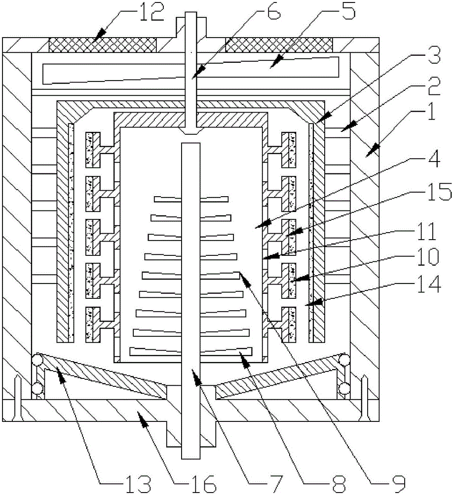
[0024] Such as figure 1 As shown, the present invention is a micropowder manufacturing equipment, comprising a closed outer cylinder, a discharge cover is arranged at the bottom of the closed outer cylinder, a guide plate is arranged on the upper part of the discharge cover, and the guide plate The height of the middle part of the plate is lower than the height of the periphery of the guide plate, and several sealing rings connected with the inner wall of the closed outer cylinder are also arranged on the periphery of the guide plate, and a grinding inner cylinder is arranged in the closed outer cylinder, and the grinding The inner cylinder is a cylindrical s...


PUM


Abstract

The invention relates to a micropowder manufacturing equipment, comprising a closed outer cylinder, a grinding inner cylinder is arranged in the closed outer cylinder, a backflow gap is arranged between the outer wall of the grinding inner cylinder and the inner wall of the closed outer cylinder, and a grinding inner cylinder is sleeved with The crushing cylinder with an open bottom, a crushing gap is set between the outer wall of the crushing cylinder and the inner wall of the grinding inner cylinder; the main drive shaft is arranged on the top of the closed outer cylinder, and the main driving shaft passes through the top of the grinding inner cylinder and the grinding cylinder. The top is fixedly connected, and a number of support rings with a T-shaped cross section are arranged in an annular array on the wall of the crushing cylinder. The T-shaped bottom of the support ring is fixedly connected with the outer wall of the crushing cylinder, and a grinding ring is attached to the T-shaped top of the support ring. ; An annular friction ring is provided on the inner wall of the grinding inner cylinder; a number of discharge holes are arranged in an array at the position between the adjacent support rings on the wall surface of the grinding cylinder, and a blowing turbofan is also rotatably connected to the bottom of the closed outer cylinder. The blast turbofan extends into the inside of the crushing cylinder.

Description

technical field [0001] The invention relates to a micropowder manufacturing equipment, which belongs to the field of micropowder manufacturing equipment. Background technique [0002] Traditional micropowder manufacturing equipment generally includes a feed port and a discharge port, and a crushing mechanism is connected between the feed port and the discharge port. Therefore, the crushing mode is a single-flow path, and it is necessary to repeatedly move the material from the discharge port. The final product can only be obtained after repeated crushing at the feeding port. The process is complicated, and the loss of materials due to dust is relatively large. Contents of the invention [0003] The technical problem to be solved by the present invention is: to overcome the technical problems of the open cycle of the micro-powder manufacturing equipment in the prior art and the technical problem of high material consumption, and to provide a micro-powder manufacturing equip...

Claims


Application Information

Patent Timeline
Patent Type & Authority Applications(China)
IPC IPC(8): B02C19/00B02C23/02B02C23/22
CPCB02C19/0006B02C23/02B02C23/22
Inventor 朱宏生
Owner 扬州锦盛微粉有限公司
Why Eureka
Try Eureka