Micro-powder pulverizer

A pulverizer and micropowder technology, which is applied in the direction of grain processing, etc., can solve the problems of large loss and complicated process, and achieve the effects of low rotation noise, increased grinding area, and increased contact efficiency

Inactive Publication Date: 2016-12-14
扬州锦盛微粉有限公司
View PDF0 Cites 7 Cited by
  • Summary
  • Abstract
  • Description
  • Claims
  • Application Information

AI Technical Summary

Problems solved by technology

[0002] Traditional micropowder pulverizers generally include a feed port and a discharge port, and a crushing mechanism is connected between the feed port and the discharge port. Therefore, the crushing mode is a single-flow path, and it is necessary to repeatedly move the material from the discharge port. The final product can only be obtained after repeated crushing at the feed port. The process is complex and the loss of materials due to dust is relatively large.

Method used


Image

  • Micro-powder pulverizer

Examples


Embodiment Construction

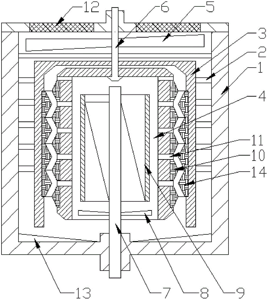
[0022] The present invention is described in further detail now in conjunction with accompanying drawing. These drawings are all simplified schematic diagrams, which only illustrate the basic structure of the present invention in a schematic manner, so they only show the configurations related to the present invention.

[0023] Such as figure 1 As shown, the present invention is a micropowder pulverizer, comprising a closed outer cylinder, an annular guide plate is arranged at the bottom of the closed outer cylinder, the height of the middle part of the guide plate is lower than the height of the periphery of the guide plate, and A grinding inner cylinder is arranged in the closed outer cylinder, and the grinding inner cylinder is detachably fixed on the inner wall of the closed outer cylinder through several connecting ribs of screw structure, and the grinding inner cylinder is a cylindrical structure with an open bottom , there is a backflow gap between the outer wall of th...


PUM


Abstract

The invention relates to a micro-powder pulverizer. The micro-powder pulverizer comprises a sealed outer cylinder, wherein a grinding inner cylinder is arranged in the sealed outer cylinder, the grinding inner cylinder is of a cylindrical structure with a bottom opening, a backflow clearance is arranged between the outer wall of the grinding inner cylinder and the inner wall of the sealed outer cylinder, a pulverizing cylinder with a bottom opening is further arranged in the grinding inner cylinder in a sleeving manner, and a pulverizing clearance is arranged between the outer wall of the pulverizing cylinder and the inner wall of the grinding inner cylinder; the top of the sealed outer cylinder is provided with a main driving shaft, the main driving shaft penetrates through the top of the grinding inner cylinder and is fixedly connected with the top of the pulverizing cylinder, and a plurality of grinding rings are arranged on the wall surface of the pulverizing cylinder in a manner of an annular array; the inner wall of the grinding inner cylinder is provided with a plurality of friction rings, and the friction rings are arranged between the adjacent two grinding rings; and a plurality of discharging holes are further arranged in positions corresponding to gaps between the adjacent grinding rings on the wall surface of the pulverizing cylinder in a manner of an array, the bottom of the sealed outer cylinder is further connected with a blast turbofan in a rotating manner, and the blast turbofan extends into the pulverizing cylinder from the bottom opening of the pulverizing cylinder.

Description

technical field [0001] The invention relates to a fine powder pulverizer, which belongs to the field of fine powder manufacturing equipment. Background technique [0002] Traditional micropowder pulverizers generally include a feed port and a discharge port, and a crushing mechanism is connected between the feed port and the discharge port. Therefore, the crushing mode is a single-flow path, and it is necessary to repeatedly move the material from the discharge port. The final product can only be obtained after repeated crushing at the feeding port. The process is complicated, and the loss of materials due to dust is relatively large. Contents of the invention [0003] The technical problem to be solved by the present invention is: to overcome the technical problem of the open cycle of the micropowder pulverizer in the prior art and the technical problem of high material consumption, and to provide a pulverizer with a closed pulverization circuit. [0004] The technical s...

Claims


Application Information

Patent Timeline
IPC IPC(8): B02C19/00B02C23/02B02C23/22
CPCB02C19/0006B02C23/02B02C23/22
Inventor 朱宏生
Owner 扬州锦盛微粉有限公司
Why Eureka
Try Eureka