
Replaceable fluid supply device

A fluid supply device and fixing seat technology, applied in auxiliary devices, auxiliary welding equipment, welding/cutting auxiliary equipment, etc., can solve the problems of low production efficiency, time-consuming and laborious, slow production speed, etc.

Inactive Publication Date: 2016-11-23
HSIN CHONG MACHINERY WORKS
View PDF6 Cites 0 Cited by
  • Summary
  • Abstract
  • Description
  • Claims
  • Application Information

AI Technical Summary

Problems solved by technology

[0003] However, this kind of manual replacement operation is not only time-consuming and laborious, but also causes slow production speed and low production efficiency.

Method used


Image

  • Replaceable fluid supply device
  • Replaceable fluid supply device
  • Replaceable fluid supply device

Examples


Embodiment Construction

[0050] The detailed description and technical content of the present invention are described below with accompanying drawings. However, the attached drawings are provided for reference and illustration only, and are not intended to limit the present invention.

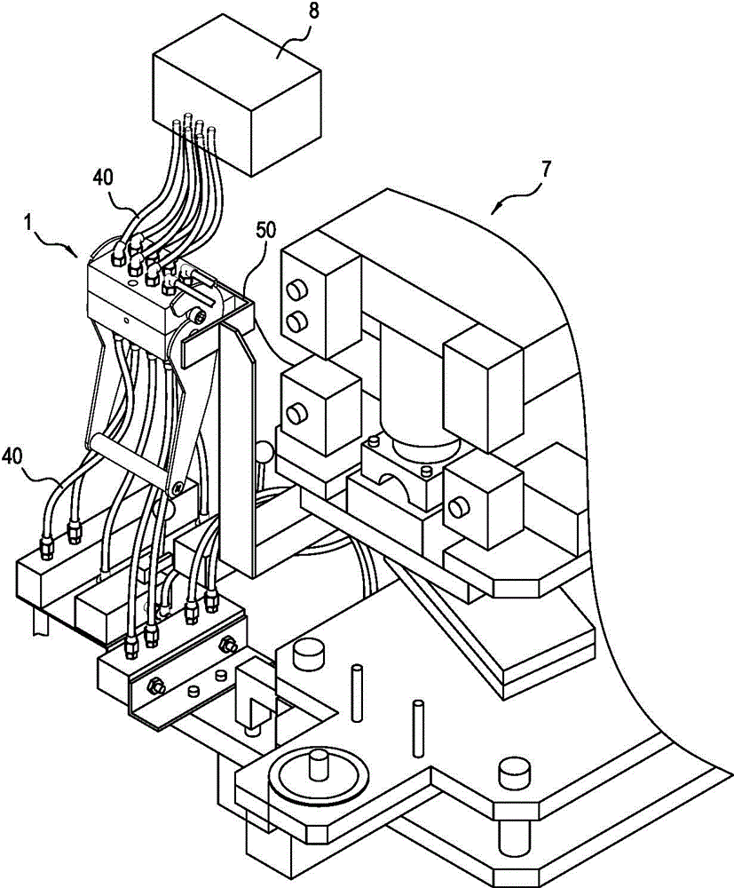
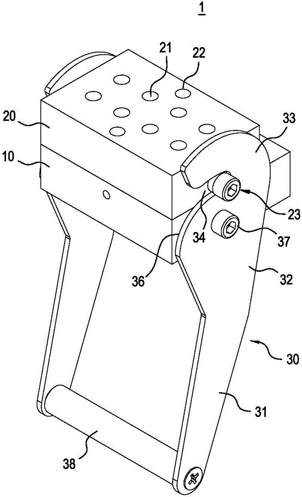
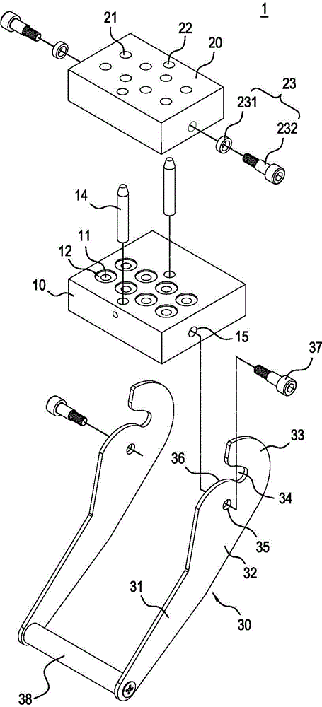
[0051] see Figure 1 to Figure 3 As shown, the present invention provides a replaceable fluid supply device, which can be applied to a welding tool 7, but is not limited to such a tool. The replaceable fluid supply device 1 mainly includes a fixing seat 10 . A detachable module 20 and a turning arm 30 .

[0052] The fixing seat 10 is made of metal and other materials, and is roughly in the shape of a rectangular block. Two rows of parallel through holes 11 are provided on the fixing seat 10, and a recess 12 is formed around the outer periphery of each through hole 11. This cavity 12 is provided with a sealing ring 13 (see Figure 5 ) installation, in addition, a positioning pin 14 is respectively connected to the fro...


PUM


Abstract

The invention relates to a replaceable fluid supply device. The replaceable fluid supply device comprises a fixed base, a detachable module and a pulling arms; the fixed base is provided with a plurality of through holes; the detachable module is correspondingly combined with the fixed base and is provided with a plurality of butt joint holes communicating with the through holes, and protruding columns are connected to side edges of the detachable module; and each pulling arm is connected to one side edge of the fixed base in a pivoted mode and is provided with a guide groove, and the guide grooves are used for fastening the protruding columns in a rotating mode. Thus, the replacement procedure can be simplified, and fast replacement work can be realized.

Description

technical field [0001] The invention relates to a fluid supply device, in particular to a replaceable fluid supply device. Background technique [0002] Generally, when it is desired to combine two metal objects, the most commonly used combination method is to achieve it through welding machines, and during the welding operation process of welding machines, and because of different welding parameters, it must be done by the operators on a regular basis. Change and replace various welding gases and cooling liquids. [0003] However, this manual replacement operation is not only time-consuming and labor-intensive, but also causes slow production speed and low production efficiency. Therefore, how to design a fluid supply device that can improve the above-mentioned technical deficiencies, so as to be used by welding machines, is an urgent problem to be solved at present. Contents of the invention [0004] In view of this, the main purpose of the present invention is to prov...

Claims


Application Information

Patent Timeline
IPC IPC(8): B23K37/00
Inventor 邱煜康曹春荣
Owner HSIN CHONG MACHINERY WORKS
Learn More