Two-way tire pressure monitoring system of single LF transmitting part

A tire pressure monitoring system and component technology, applied in tire measurement, vehicle parts, tire parts, etc., can solve the problems of long positioning time, uncontrollable measurement timing, and complex positioning process.

Active Publication Date: 2016-11-23
汪浩 +1
View PDF8 Cites 7 Cited by
  • Summary
  • Abstract
  • Description
  • Claims
  • Application Information

AI Technical Summary

Problems solved by technology

[0005] Another important performance index of the tire pressure monitoring system is the automatic positioning function. Each tire pressure sensor attachment of the two-way device is equipped with an LF transmitting antenna, and its scope is limited to this tire pressure sensor, so the tire pressure sensor can be quickly monitored at any time. Positioning; one-way devices generally cannot be automatically positioned, and need to be manually positioned with a learner or a locator; recently, there is an automatic positioning method based on measuring the turning radius difference of each tire when the vehicle turns, such as the method proposed by the publication number CN105480029A, and based on the vehicle The method of automatic positioning due to the change of tire pressure caused by the acceleration of the acceleration, but because the timing of the acceleration measurement of the one-way device is uncontrollable, the positioning process is complicated and the positioning time is long
[0006] It can be seen that the performance of the two-way device is better than that of the one-way device in all aspects, but compared with the one-way device, the two-way device needs to increase the LF emission components equal to the number of tires, and the manufacturing and installation costs are much higher than the one-way system. Competitive products in China's domestic market under cost pressure are almost all one-way systems

Method used


Image

  • Two-way tire pressure monitoring system of single LF transmitting part
  • Two-way tire pressure monitoring system of single LF transmitting part
  • Two-way tire pressure monitoring system of single LF transmitting part

Examples


Embodiment Construction

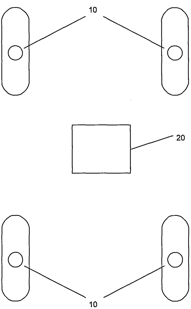
[0097] The present invention is described in detail below with specific embodiments, image 3 It is a preferred structure of a two-way tire pressure transmission monitoring system with a single LF emitting component, which includes: a control terminal 20, and four tire pressure sensors 10 installed on tires.

[0098] The structure of the control terminal 20 is as Figure 4As shown, it includes MCU200, LF transmitting part 201, RF receiving part 202, and bus interface 203 of the vehicle; For receiving the measurement data of each tire pressure sensor, the MCU 201 is connected with the bus interface 203 of the vehicle for obtaining the vehicle running status and transmitting the measurement results, and the MCU 200 is also used for controlling the work of the various components.

[0099] Each component of the control terminal 20 is installed in a housing, and is fixed on the chassis below the gear of the vehicle at the same distance as possible from the four tires. The transmis...


PUM


Abstract

The invention relates to a two-way tire pressure monitoring system which comprises a receiving controller and a plurality of tire pressure sensors. The two-way tire pressure monitoring system is characterized in that the receiving controller comprises a built-in LF transmitter, one-to-one or one-to-many communication is conducted on the tire pressure sensors through the design of two IDs, the tire pressure sensors work in a passive state, and the receiving controller sends a command through the LF transmitter to trigger the function operation of the tire pressure sensors. The manufacturing and installing cost of a device in the prior art is greatly reduced, all functions including the instant awakening function, the dormancy function and the automatic positioning function of the tire pressure sensors in the prior art can be achieved, the energy consumption of the tire pressure sensors is lower, the monitoring strategy can be dynamically adjusted according to working conditions, and the monitoring safety is improved.

Description

technical field [0001] The invention belongs to the technical field of auto parts, in particular to a two-way tire pressure monitoring system. Background technique [0002] Tire pressure monitoring system is installed in more and more vehicles because it can improve vehicle driving safety, reduce fuel consumption and avoid tire damage due to air leakage. The tire pressure monitoring system has one-way and two-way points, including several tire pressure sensors and a receiving terminal: the tire pressure sensor is installed in each tire of the vehicle, powered by a battery, and the tire pressure sensor usually includes a tire pressure sensor IC, Composed of RF antenna and matching circuit, LF antenna and matching circuit, the sensor IC has built-in pressure sensor, acceleration sensor, temperature sensor, RF transmitting circuit, LF receiving circuit, and MCU, etc. The sensor IC has a serial number that can be considered as unique Generally, this serial number is used as an ...

Claims


Application Information

Patent Timeline
Patent Type & Authority Applications(China)
IPC IPC(8): B60C23/04
CPCB60C23/0438
Inventor 汪浩黄一平
Owner 汪浩
Why Eureka
Try Eureka