An automatic cover removal device for electronic connectors

A technology of electronic connectors and power devices, which is applied in the field of automatic cover removal devices, can solve problems such as low work efficiency, lower product qualification rate, and deformation of electronic connectors, and achieve the effects of reducing costs, increasing qualification rates, and improving production efficiency

Active Publication Date: 2018-03-27
SUZHOU JUNCHANG COMM TECH CO LTD
View PDF6 Cites 0 Cited by
  • Summary
  • Abstract
  • Description
  • Claims
  • Application Information

AI Technical Summary

Problems solved by technology

However, after the heat treatment is completed, the electronic connector needs to remove the end cap. However, the current cap removal method is manual cap removal. It will cause damage to the surface of the electronic connector, and even deform the electronic connector when the cover is removed, thereby reducing the qualified rate of the product

Method used


Image

  • An automatic cover removal device for electronic connectors
  • An automatic cover removal device for electronic connectors
  • An automatic cover removal device for electronic connectors

Examples


Embodiment 1

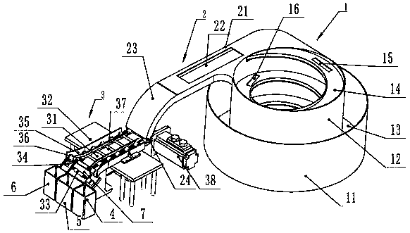
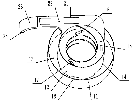
[0021] Such as Figure 1 to Figure 3 As shown, in this embodiment, the electronic connector 33 and the connector are actually the same component.

[0022] Such as figure 1 , figure 2 and image 3 As shown, an automatic capping device for electronic connectors, the automatic capping device needs to be used in conjunction with an automatic feeding device for electronic connectors.

[0023] The automatic feeding device 1 for electronic connectors includes a vibrating plate, which is provided with a spiral connector conveying track 14 for horizontally arranging and transporting the connectors, the width of the connector conveying track 14 and two ends are installed The length of the electronic connector 33 of the end cap 34 is suitable, and the described connector conveying track 14 is provided with a rejecting structure for rejecting the electronic connector 33 of the band end cap 34 arranged in disorder;

[0024] The capping device 3 includes a conveyer belt 31 driven by a ...

Embodiment 2

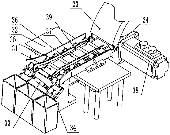
[0035] The structure of this embodiment is basically the same as that of Embodiment 1, except that the setting positions of the strip holes are different. In this embodiment, both sides of the conveyor belt 31 on the workbench 32 are provided with end cover guide grooves 35 , the end cap guide groove 35 includes a groove bottom, an outer groove plate and an inner groove plate 39, and the outer groove plate is used as a cover side plate, and the cover strip hole 36 is arranged on the outer groove plate, and the two end caps The outside groove plate of guide groove 35 mirror image is set, and the distance between the upstream end of the outside groove plate of two end cover guide grooves 35 is less than the distance between the downstream ends of the outside groove plate of two end cover guide grooves 35, and two The distance between the downstream ends of the outer side slot plates of each end cover guide groove 35 is greater than the length of the electronic connector 33 on whi...


PUM


Abstract

The invention discloses an automatic cap removal device for electronic connectors. The automatic cap removal device comprises a conveyor belt driven by a conveying power device. The conveyor belt is mounted on a workbench and provided with a plurality of feeding clamping grooves allowing the electronic connectors to be embedded therein conveniently. Cap removal side plates extending along the conveyor belt are arranged on the workbench and located on the two sides of the conveyor belt. The cap removal side plates are provided with strip-shaped cap removal holes, the upstream ends of the strip-shaped cap removal holes are open so that the ends of the electronic connectors can transversely penetrate into the strip-shaped cap removal holes conveniently, the distance between every two strip-shaped cap removal holes is gradually increased from the upstream ends to the downstream ends, and the cap removal side plates and end caps are in extrusion fit to extrude and push the end caps outwards. By means of the automatic cap removal device, automatic separation of the end caps and the electronic connectors can be achieved, automatic cap removal is achieved, cap removal efficiency is improved, the electronic connectors are prevented from being damaged, and the product percent of pass is increased.

Description

technical field [0001] The invention relates to an automatic cover-removing device, in particular to an automatic cover-removing device for an electronic connector. Background technique [0002] Electronic connectors need to be heat treated during the manufacturing process, and the end of the electronic connector has several axial groove structures. Therefore, in order to reduce the deformation of the end of the electronic connector during heat treatment, it is necessary to The two ends of the connector are equipped with an end cap to limit the deformation of the end, so that the specifications of the electronic connector after heat treatment meet the requirements, and the qualified rate of the product is higher. However, after the heat treatment is completed, the electronic connector needs to remove the end cap. However, the current cap removal method is manual cap removal. It will cause damage to the surface of the electronic connector, and even deform the electronic conn...

Claims


Application Information

Patent Timeline
Patent Type & Authority Patents(China)
IPC IPC(8): B65B69/00
CPCB65B69/00
Inventor 杜跃娣陈磊朱延花
Owner SUZHOU JUNCHANG COMM TECH CO LTD
Why Eureka
Try Eureka