
Extensible guiding hook arrangement device

A yarn guide hook and installation position technology, applied in textiles and papermaking, etc., can solve the problem of not being able to achieve the best yarn performance, and achieve the effect of optimizing the yarn forming performance and improving the yarn forming performance.

Inactive Publication Date: 2016-11-23
YANCHENG INST OF TECH
View PDF6 Cites 0 Cited by
  • Summary
  • Abstract
  • Description
  • Claims
  • Application Information

AI Technical Summary

Problems solved by technology

The current fixed phase on the self-twisting spinning machine can no longer meet the requirements of achieving the best yarn performance

Method used


Image

  • Extensible guiding hook arrangement device
  • Extensible guiding hook arrangement device
  • Extensible guiding hook arrangement device

Examples


Embodiment Construction

[0019] Accompanying drawing non-restrictively discloses the structural representation of preferred embodiment involved in the present invention; Below in conjunction with accompanying drawing

[0020] The technical solution of the present invention is described in detail.

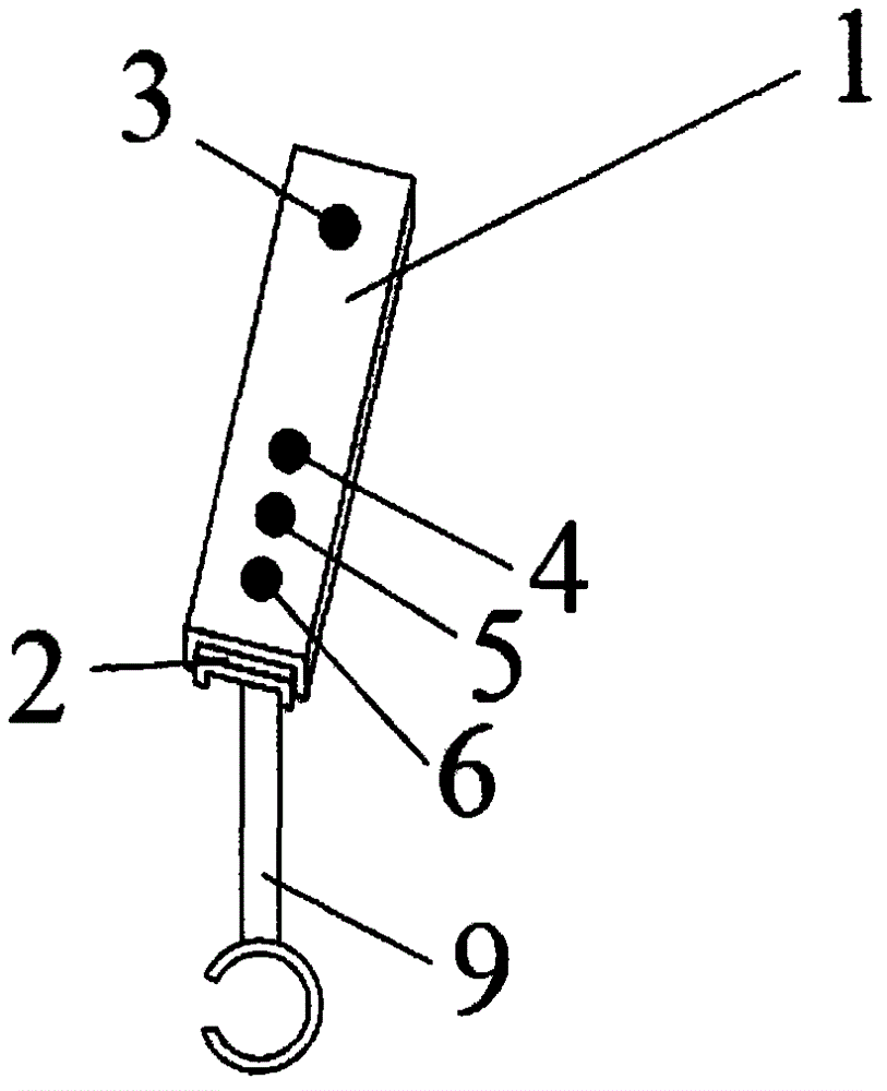
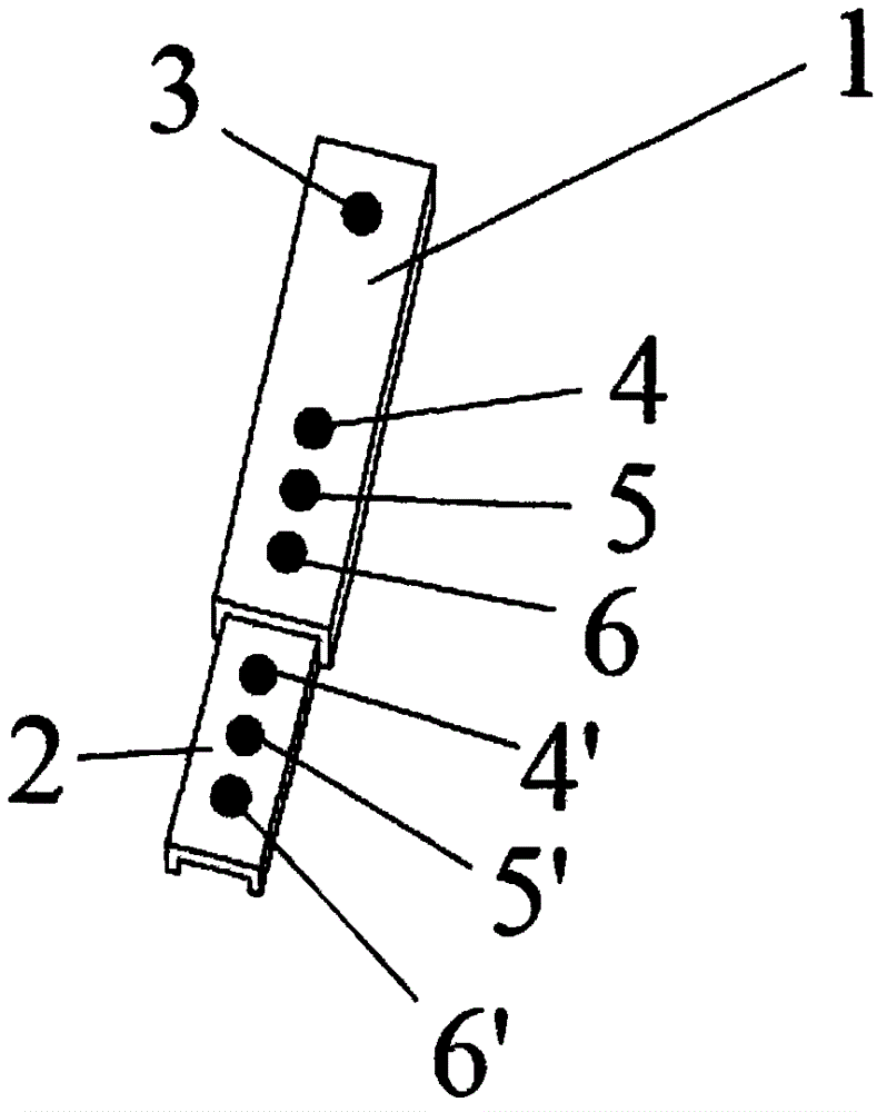
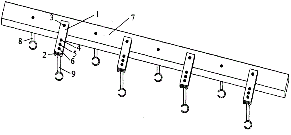
[0021] like figure 1 , figure 2 , image 3 As shown, the retractable yarn guide hook placement device of the present invention includes a placement support 1, a placement support 2, a mounting hole 3, a yarn guide hook 8, a yarn guide hook 9 and screws.

[0022] in:

[0023] The described support 1 and support 2 are in fact rods, and the support 2 is placed in the groove of the support 1 and can be stretched. When spinning with a smaller phase, use holes 4, 5, and 6 on the placement support 1 to install the guide hooks. When a larger phase is required, pull out the placement support 2 and install the guide hooks. Spinning is carried out on hole positions 4', 5', 6'. There are three positions on the p...


PUM


Abstract

The invention discloses an extensible guiding hook arrangement device, which comprises a guiding hook arrangement support 1 and an arrangement support 2, wherein the arrangement support 1 and the arrangement support 2 are fixedly arranged on a guiding hook supporting frame 7 through holes 3, the arrangement support 2 is inlaid in the middle of the arrangement support 1 and can extend, a plurality of installation sites for arranging guiding hooks are arranged on the arrangement support 2 of the arrangement device, the arrangement support 2 can still provide a plurality of installation sites for arranging guiding hooks after extending out from the arrangement support, and each guiding hook can be fixedly arranged on the arrangement support through any one installation site. Therefore, different phase positions can be obtained between a guiding hook combination part 9 and a guiding hook combination part 8 through the arrangement at the different installation sites on the arrangement support 1 and the arrangement support 2, so that different performances of the spinning yarns can be obtained.

Description

technical field [0001] The invention relates to a retractable yarn guide hook placement device, in particular to a phase-adjustable yarn guide hook placement device, which is applied to a self-twisting spinning machine. Background technique [0002] Self-twisting spinning relies on the self-twisting roller to reciprocally twist the two drawn strands at the same time, and then the two yarns that have obtained the same twist are untwisted and merged at the same time to form a yarn, and the two yarns reach the convergence through the self-twisting roller The difference in the distance of the hooks will cause a phase difference between the two yarns. When the distance is equal, it is called the same phase yarn, and when the distance is not equal, it is called the phase yarn. The breaking strength of the self-twisting yarn phase yarn with the same linear density is greater than that of the same phase yarn. The current fixed phase on self-twisting spinning machines can no longer ...

Claims


Application Information

Patent Timeline
IPC IPC(8): D01H13/04
Inventor 崔红高秀丽陆振乾
Owner YANCHENG INST OF TECH
Learn More