Passive and inactive integrated water stop middle buried type water stop belt structure for construction joint

A technology of active and passive construction joints, applied in underwater structures, infrastructure engineering, artificial islands, etc., can solve problems affecting the normal operation of tunnels and underground engineering, endangering structural durability, and detailed waterproof defects, etc., to achieve engineering quality Easier to control, save construction cost, simple and feasible effect

Inactive Publication Date: 2016-11-23
中铁二院重庆勘察设计研究院有限责任公司
View PDF9 Cites 2 Cited by
  • Summary
  • Abstract
  • Description
  • Claims
  • Application Information

AI Technical Summary

Problems solved by technology

However, due to the level of construction and technology, the shrinkage and creep of concrete, and the performance differences between waterproof materials and concrete, etc., there are defects in detailed waterproofing, and leakage of water in details such as deformation joints and construction joints has become a prominent engineering problem in current tunnel and underground projects.
Tunnels and underground projects are mostly reinforced concrete structures. Groundwater invades the main body of the structure, causing corrosion of steel bars and deterioration of concrete, which endangers the durability of the structure. At the same time, it affects the normal operation of tunnels and underground projects and increases operating costs.

Method used


Image

  • Passive and inactive integrated water stop middle buried type water stop belt structure for construction joint
  • Passive and inactive integrated water stop middle buried type water stop belt structure for construction joint

Examples


Embodiment Construction

[0019] Below in conjunction with accompanying drawing and embodiment the present invention will be further described:

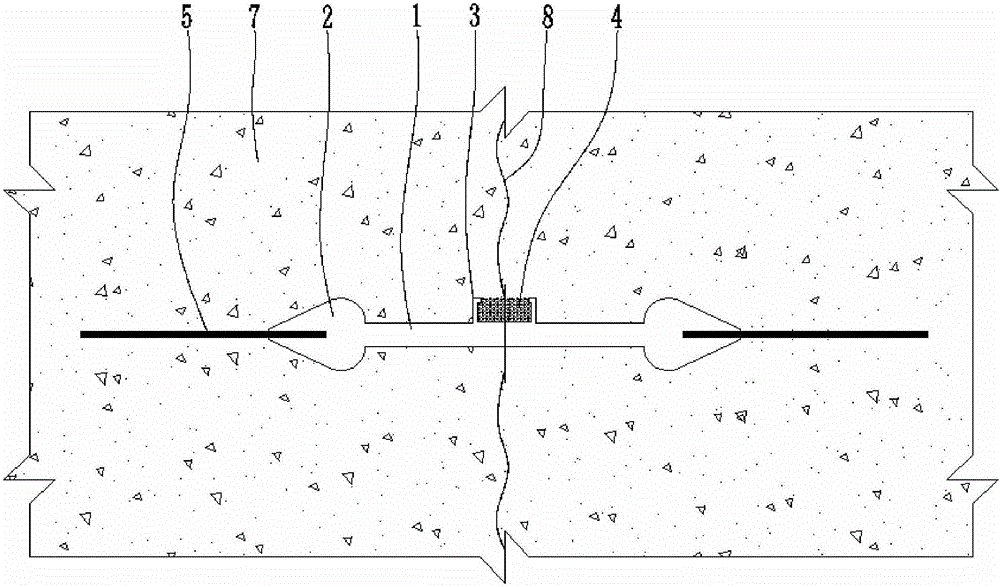
[0020] Such as figure 1 , figure 2 As shown, it is defined that the left-right direction shown in the figure is the width direction of the main belt body 1, and the direction perpendicular to the paper surface is the length direction of the main belt body 1. The main belt body 1 is preferably formed by extrusion molding, and an upwardly protruding middle convex bag 3 is integrally formed in the middle part of the main belt body 1 top surface. The middle part convex bag 3 extends along the length direction of the main belt body 1. The middle convex bag 3 The front and rear ends are flush with the corresponding end faces of the main belt body 1 . The top of the middle convex bag 3 is provided with an opening or a water inlet hole. In the present embodiment, the middle convex bag 3 is preferably a rectangular through groove with a notch on the top, and the up...


PUM


Abstract

The invention discloses a passive and inactive integrated water stop middle buried type water stop belt structure for a construction joint. A middle convex bag protruding upwards is integrally formed at the middle portion of the top face of a main belt body. An opening or a water inlet hole is formed in the top of the middle convex bag. A convex bag water encountering expansion body matched with the inner cavity of the middle convex bag is arranged in the inner cavity of the middle convex bag. Side bosses are arranged at the two ends of the main belt body in the width direction. Metal positioning pieces are fixedly arranged on the outer sides of the side bosses on the two sides. According to the passive and inactive integrated water stop middle buried water stop belt structure, active water blocking of the main belt body of a water stop belt, the middle convex bag and the metal positioning pieces is achieved, the water encountering expansion body in the middle convex bag expands when encountering water to passively block water, and the multi-way water blocking target is achieved. Active waterproofing and passive waterproofing are combined, water is blocked in multiple ways, and the water blocking effect is good. The middle convex bag has protecting and restraining effects on the water encountering expansion body, and the water blocking effect can be improved. The passive and inactive integrated water stop belt structure is easy and feasible to implement, the construction cost can be saved, the project quality is easy to control, water is blocked outside the water incoming side, and durability of a concrete structure is good.

Description

technical field [0001] The invention belongs to the technical field of waterproofing of tunnels and underground engineering, and in particular relates to a mid-buried waterstop structure for active and passive integrated waterstopping of construction joints. Background technique [0002] At present, tunnels and underground projects generally adopt the principle of waterproofing the main body of the structure, and focusing on the waterproofing of detailed structures such as deformation joints and construction joints. However, due to the level of construction and technology, the shrinkage and creep of concrete, and the performance differences between waterproof materials and concrete, etc., there are defects in detailed waterproofing, and water leakage in details such as deformation joints and construction joints has become a prominent engineering problem in current tunnel and underground projects. Tunnels and underground projects are mostly reinforced concrete structures, and...

Claims


Application Information

Patent Timeline
Patent Type & Authority Applications(China)
IPC IPC(8): E02D29/16E02D31/02E21D11/38
CPCE02D29/16E02D31/02E21D11/38
Inventor 李海军
Owner 中铁二院重庆勘察设计研究院有限责任公司
Why Eureka
Try Eureka