Supporting equipment based on adjustment on projection positions and angles on ground

A technology of projection position and angle, applied in the direction of supporting machines, machines/brackets, mechanical equipment, etc., can solve the problems of narrow use range and adjustment of use requirements, and achieve the effect of firm installation and expansion of use range

Active Publication Date: 2016-11-23
CHENGDU ZHIRONG ZHICHUANG INTPROP MANAGEMENT CO LTD
View PDF5 Cites 0 Cited by
  • Summary
  • Abstract
  • Description
  • Claims
  • Application Information

AI Technical Summary

Problems solved by technology

[0003] The purpose of the present invention is to overcome the problem that the above-mentioned existing projector is installed on the ceiling by a bracket and the installation position is fixed, resulting in a narrow range of use and cannot be adjusted according to people's use requirements. Supporting equipment, the installation equipment projects the projector towards the ground, and the installation is firm, the installation height and projection angle can be adjusted, which expands the scope of use, and solves the problem that the installation position of the existing projector is fixed to the ceiling through the bracket. The problem that the scope of use is narrow and cannot be adjusted according to people's requirements

Method used


Image

  • Supporting equipment based on adjustment on projection positions and angles on ground

Examples


Embodiment

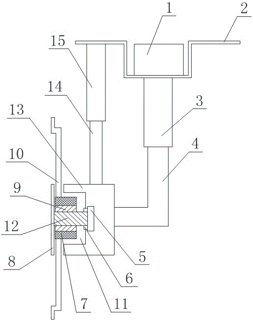
[0013] like figure 1 As shown, the supporting equipment based on adjusting the position and angle of the projection to the ground includes a mounting plate 2 that is bent downward to form a mounting groove, a hydraulic tank 1 is arranged in the mounting groove, and a hydraulic cylinder is disposed below the mounting plate 2 3, and the top of the hydraulic cylinder 3 is fixed on the bottom of the mounting plate 2 and communicated with the hydraulic tank 1, the hydraulic cylinder 3 is provided with an L-shaped hydraulic rod 4, one end of the hydraulic rod 4 is arranged in the hydraulic cylinder 3, and the other end is along the The bottom of the hydraulic cylinder 3 passes through the hydraulic cylinder 3 and is arranged outside the hydraulic cylinder 3, and the hydraulic rod 4 can move in the hydraulic cylinder 3 along the inner wall of the hydraulic cylinder 3, and a hollow mounting cover 13 is provided below the hydraulic cylinder 3 , and the installation cover 13 and the hyd...


PUM


Abstract

The invention discloses supporting equipment based on adjustment on projection positions and angles on the ground. The supporting equipment is characterized in that an assembly plate is bent downwards to form an assembly tank; a hydraulic box is arranged in the assembly tank; a hydraulic cylinder is arranged below the assembly plate; an L-shaped hydraulic rod is arranged in the hydraulic cylinder; the hydraulic rod penetrates through the hydraulic cylinder along the bottom of the hydraulic cylinder and is arranged outside the hydraulic cylinder; an assembly shield is arranged below the hydraulic cylinder; the assembly shield is fixedly connected with the hydraulic rod; a telescopic device is arranged between the assembly shield and the assembly plate; a supporting plate is arranged outside the assembly shield; a fixed shaft is arranged between the supporting plate and the assembly shield; a limiting plate is arranged on the fixed shaft; a connection ring sleeves the outer wall of the fixed shaft; the outer wall of the fixed shaft is sleeved with a bearing; the outer wall of the bearing is sleeved with a sleeve; and the outer wall of the sleeve is provided with a fixing bar. The assembly equipment enables a protector to face to the ground for projection; assembly is firm; assembly heights and projection angles can be adjusted; and the use range is enlarged.

Description

technical field [0001] The invention relates to an installation device, in particular to a support device based on adjusting the position and angle of projection to the ground. Background technique [0002] Projection is a kind of optical technology to realize image. A projector, also known as a projector, is a device that projects or reflects images or videos onto the screen through digital light processing technology or LCD liquid crystal imaging technology. Image and video signals for playback. Projectors are widely used in education, business, engineering, household and other places. According to the working principle, projectors are mainly divided into DLP, LCD and other types. DLP is digital light processing imaging technology. In short, the image signal is digitally processed, and then the light is projected out. It is based on the digital micromirror component developed by TI (Texas Instruments) - DMD to complete the technology of visual digital information disp...

Claims


Application Information

Patent Timeline
Patent Type & Authority Applications(China)
IPC IPC(8): F16M13/02F16M11/06F16M11/04
CPCF16M11/04F16M11/06F16M13/02
Inventor 谢义刚
Owner CHENGDU ZHIRONG ZHICHUANG INTPROP MANAGEMENT CO LTD
Why Eureka
Try Eureka