
A skeletonless optical fiber current sensing loop and its manufacturing method

A technology of sensing loops and optical fiber loops, applied in the direction of voltage/current isolation, fiber mechanical structure, etc., can solve the problem of affecting the measurement accuracy of optical fiber current transformers, the skeleton is easily affected by external temperature changes, and the sensing loop produces effects and other problems, to achieve the effect of high reliability, simple production and reasonable scheme

Active Publication Date: 2019-01-01
BEIJING AUTOMATION CONTROL EQUIP INST
View PDF3 Cites 0 Cited by
  • Summary
  • Abstract
  • Description
  • Claims
  • Application Information

AI Technical Summary

Problems solved by technology

[0004] The technical problem to be solved in the present invention is: the skeleton with the skeleton sensing ring is easily affected by the change of external temperature, thus exerting an effect on the sensing ring and affecting the measurement accuracy of the optical fiber current transformer

Method used


Image

  • A skeletonless optical fiber current sensing loop and its manufacturing method
  • A skeletonless optical fiber current sensing loop and its manufacturing method
  • A skeletonless optical fiber current sensing loop and its manufacturing method

Examples


Embodiment Construction

[0031] A skeletonless optical fiber current sensing loop and its manufacturing method of the present invention will be described in detail below with reference to the drawings and embodiments.

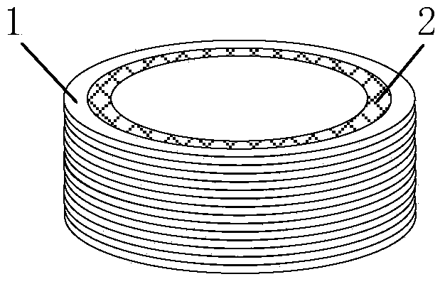
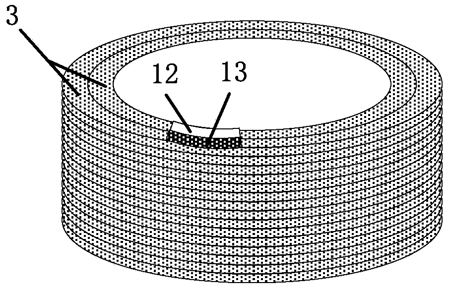
[0032] The shape of the skeletonless optical fiber current sensing loop of the present invention is as follows figure 2 As shown, it includes an optical cable 3, a mirror 12 and a 1 / 4 wave plate 13. The optical cable 3 is firstly circled from top to bottom, and then from bottom to top to form two circles inside and outside, and two adjacent optical cables 3 are closely arranged and bonded with ultraviolet curing glue 9; the starting end of the optical cable 3 Set side by side with the end end, the start end is connected with the reflector 12, and the end end is connected with the 1 / 4 wave plate 13,

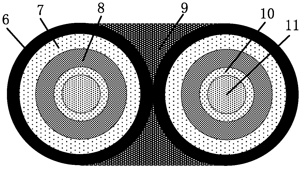
[0033] Such as image 3 As shown, the optical cable 3 is composed of: polyethylene sheath 6, aramid yarn 7, loose tube 8, casing filling oil 10 and bare spun optical fiber 11, the cente...


PUM


Abstract

The invention belongs to the technical field of an electric power system, and specifically relates to a frameless optical fiber current sensing ring and a manufacturing method thereof. The frameless optical fiber current sensing ring comprises an optical cable, a reflecting mirror and a 1 / 4 wave plate, and is characterized in that the optical cable is wound into an inner ring and an outer ring in a mode of being first from top to bottom and then from bottom to top, and the adjacent two optical cables are compactly arranged and bound by an ultraviolet curing adhesive; the starting end and finishing end of the optical cable are arranged side by side, the starting end is connected with the reflecting mirror, and the finishing end is connected with the 1 / 4 wave plate. The frameless optical fiber current sensing ring solves a problem that a framework of a framed sensing ring is susceptible to external temperature variations, thus an effect is generated for the sensing ring, and the measurement precision of an optical fiber current transformer is affected. The birefringence of a sensitive optical fiber of the frameless optical fiber current sensing ring provided by the invention is not easy to be affected by the external environmental temperature variations, the total temperature measurement precision is good in stability and high in reliability, and the measurement precision is ensured.

Description

technical field [0001] The invention belongs to the technical field of power systems, and in particular relates to a frameless optical fiber current sensing loop and a manufacturing method thereof. Background technique [0002] Optical fiber current transformer is a photoelectric sensor based on the Faraday effect. It has the characteristics of good insulation, no magnetic saturation and high safety. It is an ideal product to replace traditional current transformers and has an irreplaceable role in the new generation of intelligent substations. status and broad market prospects. At present, the optical path scheme commonly used in fiber optic current transformers at home and abroad is the straight waveguide reflection type. The advantage of this scheme is that two beams of light waves can be strictly "synchronized" on the same path through a reflector to achieve a "fully symmetrical" optical path. This means that it has better anti-interference ability, which can greatly r...

Claims


Application Information

Patent Timeline
Patent Type & Authority Patents(China)
IPC IPC(8): G01R15/24G02B6/44
Inventor 杨怿吴衍记许刚向强章敏段俊杰
Owner BEIJING AUTOMATION CONTROL EQUIP INST
Learn More