
Current detection device and current detection method

A current detection device and current detection technology are applied in the direction of measurement device, measurement of current/voltage, measurement of electrical variables, etc., and can solve the problems of complex structure, complicated circuit, and small detection angle of the acoustic detection device.

Inactive Publication Date: 2016-11-23
贺遒翔 +2
View PDF6 Cites 7 Cited by
  • Summary
  • Abstract
  • Description
  • Claims
  • Application Information

AI Technical Summary

Problems solved by technology

Both the optical detection device and the acoustic detection device include optical and acoustic transmitting and receiving units, and the price is relatively high
Moreover, the detection angle of a single optical and acoustic detection device is too small, often a self-moving robot is equipped with multiple optical and acoustic detection devices still have detection blind spots
And the light wave or sound wave will be absorbed when encountering light-absorbing materials, and will not be reflected, which will affect the signal reception of the detection device
As a result, the application of such detection devices on self-moving robots has complex circuits, high costs, and poor effects
However, the collision sensing devices used in self-moving robots all include more than one collision block, balance bar, spring and multiple sensing devices. The structure of the collision sensing device is complex and the cost is relatively high.

Method used


Image

  • Current detection device and current detection method
  • Current detection device and current detection method
  • Current detection device and current detection method

Examples


Embodiment 1

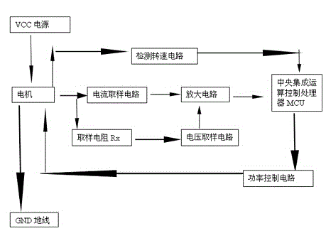
[0021] Therefore, the current value is I1 when the motor is idling, I2 when the motor is working normally, and I3 when it is blocked by an obstacle.

[0022] According to the size of the motor current, the following four situations are listed:

[0023] 1. When the measured value of the motor current is less than or equal to I1, the central integrated operation control processor MCU can judge that the motor is in an idling state through the current signal obtained. Reverse the motor to do a small back to avoid obstacles.

[0024] 2. When the measured value of the motor current is greater than I1 but less than or equal to I2, the central integrated computing control processor MCU can judge that the motor is in a normal working state through the current signal obtained, and the program determines that the self-moving robot does not need to make any adjustments.

[0025] 3. When the measured value of the motor current is greater than I2 but less than or equal to I3, the central i...


PUM


Abstract

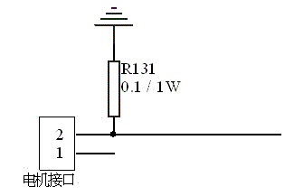
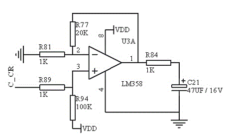
The invention discloses a current detection device and a current detection method, which particularly relate to a device and a method of judging the moving state of a self-moving cleaning robot through detecting the current strength. The current detection device is formed by combining a plurality of detection units, and is characterized in that each detection unit is formed by a motor, a sampling resistor and a 358 amplifier, the motor is serially connected with the sampling resistor, and one end of the 358 amplifier is connected with the motor. The technical problem that the existing self-moving cleaning robot needs to be equipped with multiple acoustic or optical detection devices for obstacle avoidance can be solved, the production cost of the self-moving cleaning robot can be further reduced, and the popularization is facilitated.

Description

technical field [0001] The invention relates to a current detection device and method, in particular to a device and method for judging the moving state of a self-moving cleaning robot by detecting current intensity. Background technique [0002] Most of the existing commercial self-moving cleaning robots have the function of automatically avoiding obstacles. This function is realized by detecting obstacles through sensing devices and changing the moving direction of the robot. Therefore, it is necessary to install multiple sensing devices on the self-moving robot to ensure the normal operation of the robot. Commonly used sensing devices include optical detection devices, acoustic detection devices, and collision sensing devices. Both the optical detection device and the acoustic detection device include optical and acoustic transmitting and receiving units, and the price is relatively high. Moreover, the detection angle of a single optical and acoustic detection device is ...

Claims


Application Information

Patent Timeline
Patent Type & Authority Applications(China)
IPC IPC(8): G01R19/00G05D1/02
Inventor 贺勇锋
Owner 贺遒翔
Learn More