Tractor used for cable

A tractor and cable technology, applied in the direction of cable laying equipment, etc., can solve the problems of cable surface wear, area reduction, wear, etc., to achieve the effect of easy pulling out cables, improving applicability and reducing obstacles

Inactive Publication Date: 2016-11-23
CHONGQING YINGJIE SCI & TECH CO LTD
View PDF0 Cites 4 Cited by
  • Summary
  • Abstract
  • Description
  • Claims
  • Application Information

AI Technical Summary

Problems solved by technology

Due to the limitation of the terrain, the cable steel pipe is usually bent according to the corner of the terrain or the corner of the building when laying. The other end is connected with multiple cables wrapped with adhesive tape, and then one end of the steel wire is manually pulled until the wrapped wire ends completely pass through the cable duct. During the pulling process, the straight line cable duct requires less labor. , but when the cable enters the bend of the cable duct, the cable

Method used


Image

  • Tractor used for cable
  • Tractor used for cable
  • Tractor used for cable

Examples


Embodiment 1

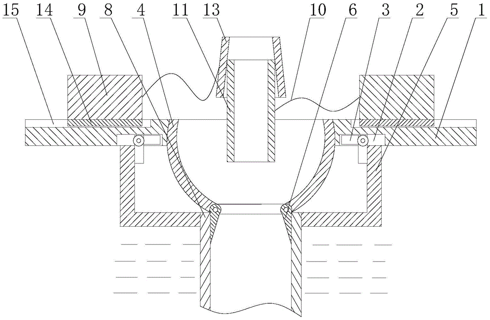
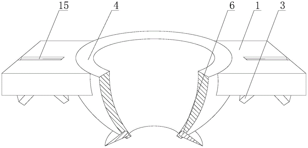
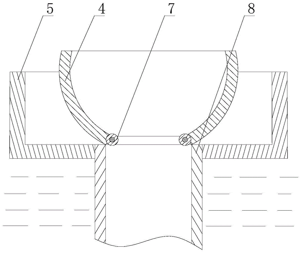
[0030] Such as Figure 1 to Figure 4 As shown, the retractor for cables includes a hemispherical body 4 with upper and lower ends open and hollow, and two supporting plates 1 fixed on both sides of the upper opening of the hemispherical body 4 respectively. The lower end surfaces of the two supporting plates 1 are all opened with In the blind hole 2, two snap-in plates 3 perpendicular to each other are rotated at the bottom of the blind hole 2 by the first torsion spring, the movable end of the snap-in plate 3 protrudes from the blind hole 2, and the edge of the opening at the lower end of the hemisphere 4 passes through the first torsion spring. The two torsion springs are rotated and provided with two oppositely arranged splints 6, and the edge is also provided with rollers 7 which are staggered with the splint 6; The sliding block 9 that the chute 15 moves and is arranged laterally, the opposite surfaces of the two sliding blocks 9 are provided with a drawing wire 10, and t...


PUM


Abstract

The invention discloses a tractor used for cable. The tractor comprises a hemisphere and two supporting plates which are fixed at the two sides of the hemisphere. The lower end surfaces of the two supporting plates are provided with blind holes. Two mutually perpendicular clamping plates are rotatably arranged at the bottom part of the blind holes through first torsional springs. The flexible ends of the clamping plates protrude out of the blind holes. The edge of the opening of the lower end of the hemisphere is rotatably provided with two clip plates through second torsional springs. The edge is also provided with rolling wheels, and the clip plates and the rolling wheels are arranged in a staggered way. The upper end surfaces of the two supporting plates are provided with slide grooves which are provided with slide blocks. The opposite surfaces of the two slide blocks are provided with drawing lines. The free end of one of the two drawing lines is fixedly connected with an internal sleeve, and the free end of the other drawing line is fixedly connected with an external sleeve which is matched with the internal sleeve in a threaded way. The internal sleeve is enabled to closely clamp a cable head through threaded matching of the external sleeve and the internal sleeve; and then the internal sleeve and the external sleeve together with the cable head can be pulled out through matching of the slide blocks and the slide grooves. Therefore, the subsequent cable drawing work is facilitated.

Description

technical field [0001] The invention relates to a power system, in particular to a tractor for cables. Background technique [0002] Power cable wiring is an important part of the power system. Power cable wiring should meet the following requirements: 1. The laying method of cable wiring should be based on factors such as engineering conditions, environmental characteristics, cable type and quantity, and meet the requirements of reliable operation, easy maintenance and 2. The selection of the cable path should meet the following requirements: 1) The cable should be protected from mechanical force, overheating, corrosion and other hazards; 2) It should be easy to lay and maintain; 3) It should be kept away from the site The planned construction land or construction land; 4) The cable path should be the shortest when the safety conditions are met; 3. When the cable is laid indoors, in the cable trench, cable tunnel and electrical shaft, the flammable outer surface should not ...

Claims


Application Information

Patent Timeline
IPC IPC(8): H02G1/08
Inventor 王建勇
Owner CHONGQING YINGJIE SCI & TECH CO LTD
Why Eureka
Try Eureka