Monitoring method, device and system based on following type virtual fence

A virtual fence and monitoring device technology, applied in the field of communication, can solve problems such as inapplicability, adverse effects on accuracy, and accuracy of positioning information, and achieve the effect of controlling the false alarm rate

Inactive Publication Date: 2016-11-23
CHINA MOBILE COMM GRP CO LTD
View PDF5 Cites 11 Cited by
  • Summary
  • Abstract
  • Description
  • Claims
  • Application Information

AI Technical Summary

Problems solved by technology

For positioning information, even if multiple methods of hybrid positioning (such as satellite + base station dual positioning) are used, there is still a deviation of about 5-10m, and it cannot be applied at all in areas where satellite positioning cannot be performed, such as indoors.
There are currently two ways to delineate the boundary range. One is to manually delineate on the map on the platform side. Unavoidably, it will have adverse effects on accuracy; the other is to use the satellite positioning information obtained by the positioning terminal itself as the center of the circle, and a circular area with a certain distance as the radius as the boundary range, but the error of the positioning information itself will affect the final accuracy
[0004] Second, the boundaries mentioned above are all fixed-point areas, but the security boundaries of many application scenarios are constantly moving (for example, the owner goes out to walk the dog, logistics vehicles transport goods, etc.), and the fixed-point security boundary area obviously cannot meet this requirement. Class Application Requirements

Method used


Image

  • Monitoring method, device and system based on following type virtual fence
  • Monitoring method, device and system based on following type virtual fence
  • Monitoring method, device and system based on following type virtual fence

Examples


Embodiment Construction

[0049] In order to make the technical problems, technical solutions and advantages to be solved by the present invention clearer, the following will describe in detail with reference to the drawings and specific embodiments.

[0050] Aiming at the problem that the fixed-point area in the virtual fence area in the prior art cannot satisfy the continuous movement of the positioning terminal, the present invention provides a monitoring method, device and system based on a follow-up virtual fence, which enables the monitored object to follow the positioning terminal in the Move freely within the virtual fence area.

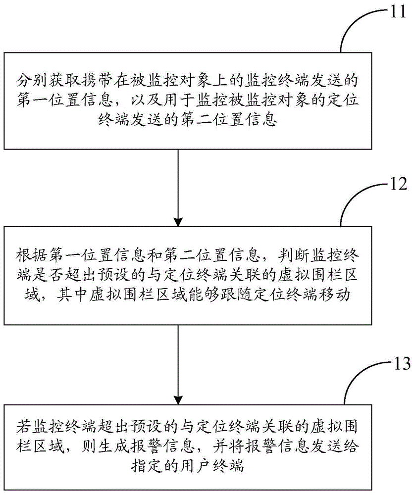
[0051] like figure 1 As shown, the embodiment of the present invention provides a monitoring method based on a follow-up virtual fence, which is applied to a cloud server, and the monitoring method includes:

[0052] Step 11, acquiring first location information sent by a monitoring terminal carried on the monitored object and second location information sent by a po...


PUM


Abstract

The invention provides a monitoring method, device and system based on a following type virtual fence. The monitoring method comprises the steps of respectively obtaining first position information which is carried on a monitored object and is sent by a monitoring terminal, and a second position information which is used for monitoring the monitored object and is sent by a positioning terminal; according to the first position information and the second position information, judging whether the monitoring terminal is beyond a present virtual fence area relevant to the positioning terminal, wherein the virtual fence area can follow the positioning terminal to move; and if the monitoring terminal is beyond the preset virtual fence area relevant to the positioning terminal, generating alarm information, and sending the alarm information to a designated user terminal. According to the scheme of the invention, the monitored object can be enabled to follow the positioning terminal to move freely in the virtual fence area.

Description

technical field [0001] The invention relates to the field of communication technology, in particular to a monitoring method, device and system based on a follow-up virtual fence. Background technique [0002] At present, with the wide application of positioning technology, the virtual fence function derived from it has been popularized. This function is to install a monitoring terminal for the monitored object, perform logical judgment processing based on real-time geographic location information and the predetermined fence boundary, trigger a predefined event, and issue a corresponding cross-border alarm message to construct a set of invisible The perimeter anti-theft alarm system achieves a more accurate security monitoring effect. However, there are at least the following defects in the implementation method of the existing virtual fence: [0003] First, the accuracy of the alarm depends entirely on the two factors of real-time positioning information and the accuracy o...

Claims


Application Information

Patent Timeline
Patent Type & Authority Applications(China)
IPC IPC(8): H04W4/02H04W24/00H04L29/08
CPCH04L67/025H04L67/10H04W4/021H04W4/023H04W24/00H04L67/52
Inventor 戴欣宛海涛范晓晖
Owner CHINA MOBILE COMM GRP CO LTD
Why Eureka
Try Eureka