Electric heating component

A technology of electric heating and components, which is applied in the direction of ohmic resistance heating components, the shape of heating elements, fluid heaters, etc., and can solve problems such as scaling, leakage, corrosion breakdown, etc.

Inactive Publication Date: 2016-11-23
GUANGDONG SHUNDE GUANGSHENG ELECTRICAL APPLIANCE
View PDF0 Cites 0 Cited by
  • Summary
  • Abstract
  • Description
  • Claims
  • Application Information

AI Technical Summary

Problems solved by technology

[0002] At present, more than 95% of the world's electric water heaters use electric heating tubes with electric heating wires in stainless steel tubes, and magnesium oxide powder separates the electric heating wires from the metal pipe wall; the electric heating tubes are soaked in water; this kind of electric heating tubes will be scaled And produce c

Method used


Image

  • Electric heating component
  • Electric heating component
  • Electric heating component

Examples


Embodiment Construction

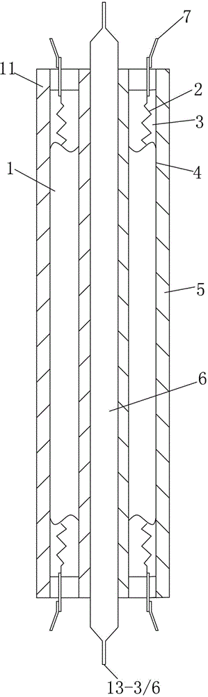
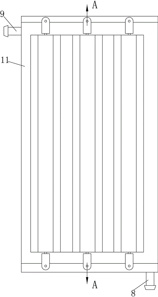
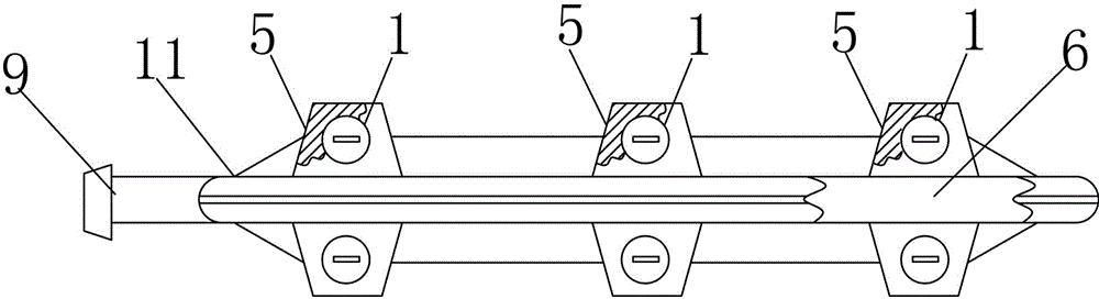
[0016] In the accompanying drawings, an electric heating component 11, an electric heating tube 1, an electric heating wire 2, magnesium oxide powder 3, a metal pipe 4, an aluminum alloy 5, a water flow channel 6 made of a metal material, a connection terminal 7, a water inlet port 8, and a water outlet port 9 .

[0017] figure 1 for figure 2 A-A sectional view, the electric heating tube 1 and the water flow channel 6 are wrapped by the aluminum alloy 5; the heat generated after the electric heating tube 1 is energized, passes through the aluminum alloy 5, and heats the water flowing in the water flow channel 6 by means of heat conduction; figure 2 is the outline drawing of the electric heating part, image 3 It is a top view; there are 6 electric heating tubes 1 in the figure, and there are 3 on each side. Depending on the structure and heating power, one or several can be used; the water flow channel 6 is flat in the figure, and can also be square or other shapes. The w...


PUM


Abstract

The electric heating part is that there is an electric heating wire 2 inside the aluminum tube 4, and the electric heating wire 2 is insulated from the aluminum tube 4 by magnesium oxide powder 3. Channel 6 is combined into one body by welding or casting.

Description

technical field [0001] The invention relates to an electric heating component, and mainly relates to an electric heating component for an electric water heater. Background technique [0002] At present, more than 95% of electric water heaters in the world use electric heating tubes with electric heating wires in stainless steel tubes, and magnesium oxide powder is used to separate the electric heating wires from the metal pipe wall; the electric heating tubes are soaked in water; this kind of electric heating tubes will be scaled And produce corrosion breakdown, make the water electrified; There are also carbon fiber electric heating tubes and halogen electric heating tubes that generate light and heat after being energized; Heat pipe: These electric heating methods have defects, such as electric leakage, easy fragmentation, power attenuation, etc. The present invention provides a new structure. Contents of the invention [0003] The present invention provides an electric...

Claims


Application Information

Patent Timeline
IPC IPC(8): H05B3/42H05B3/02F24H9/18
Inventor 刘运柳
Owner GUANGDONG SHUNDE GUANGSHENG ELECTRICAL APPLIANCE
Why Eureka
Try Eureka