
Emergency lighting controller circuit

An emergency lighting and controller technology, applied in lighting devices, electric lamp circuit layout, electric light sources, etc., can solve the problems of single direction and inability to perform dynamic indication, and achieve the effect of ensuring reliability

Inactive Publication Date: 2016-11-23
合肥联信电源有限公司
View PDF3 Cites 3 Cited by
  • Summary
  • Abstract
  • Description
  • Claims
  • Application Information

AI Technical Summary

Problems solved by technology

When a fire occurs, the emergency lighting controller circuit and the fire early warning and alarm system are linked to control, and the emergency evacuation lamps are intelligently controlled according to the on-site fire information, and the guiding direction is adjusted, which solves the problem that the existing evacuation systems mostly use non-centralized power sources. Centralized control system, each evacuation indicator light works independently, with a single direction, unable to perform dynamic indication problems

Method used


Image

  • Emergency lighting controller circuit
  • Emergency lighting controller circuit
  • Emergency lighting controller circuit

Examples


Embodiment Construction

[0032] The following will clearly and completely describe the technical solutions in the embodiments of the present invention with reference to the accompanying drawings in the embodiments of the present invention. Obviously, the described embodiments are only some, not all, embodiments of the present invention. Based on the embodiments of the present invention, all other embodiments obtained by persons of ordinary skill in the art without creative efforts fall within the protection scope of the present invention.

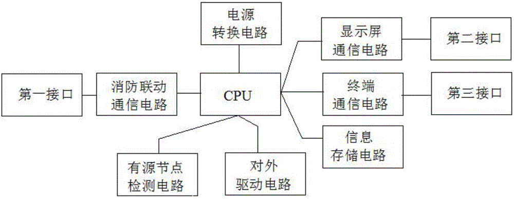
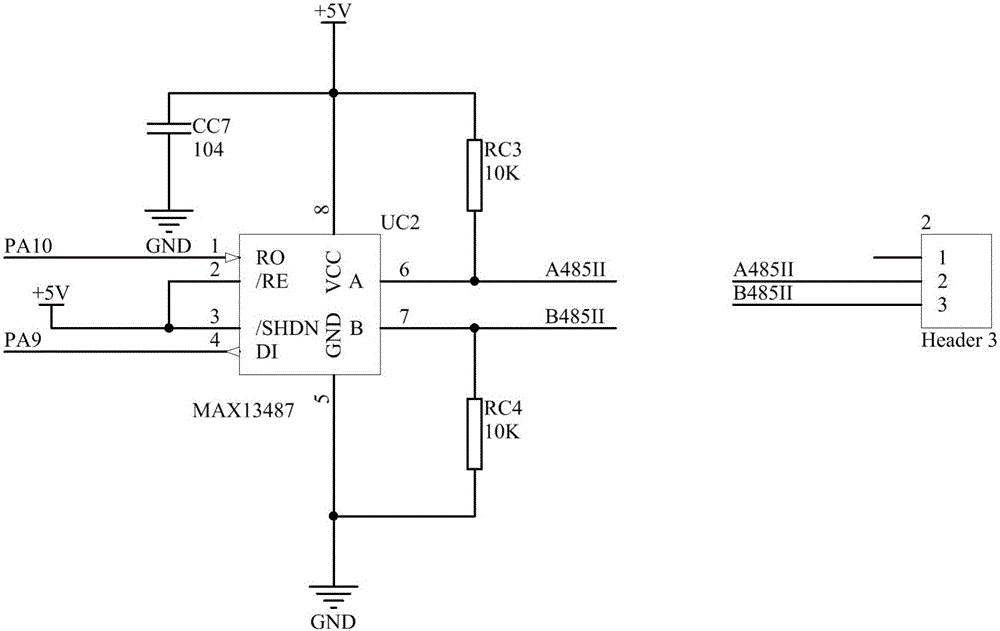
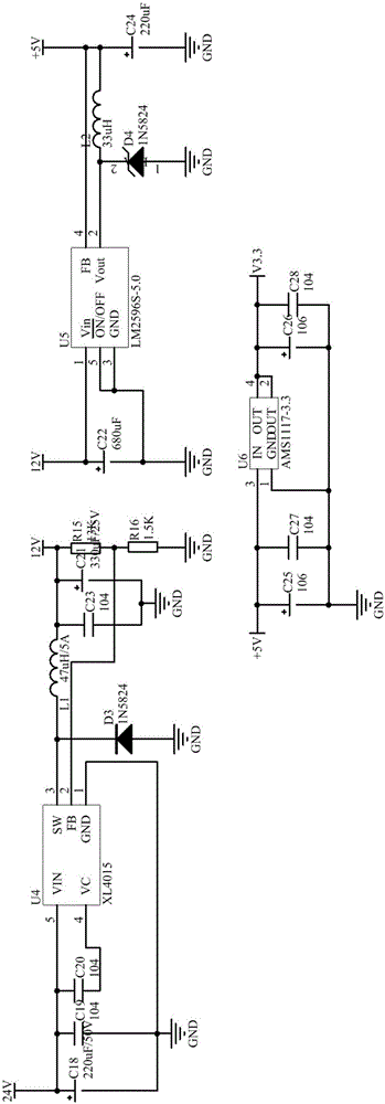
[0033] see Figure 1-5 As shown, the present invention is an emergency lighting controller circuit, including a main control CPU, a fire linkage communication circuit, a display screen communication circuit, a terminal communication circuit, a power conversion circuit, an information storage circuit, an active node detection circuit, and an external drive circuit ;

[0034] Among them, the fire linkage communication circuit is equipped with a first interface, whic...


PUM


Abstract

The invention discloses an emergency lighting controller circuit which comprises a main control CPU and a firefighting linkage communication circuit, a display screen communication circuit, a terminal communication circuit, a power switching circuit, an information storage circuit, an active node detection circuit and an external drive circuit controlled by the main control CPU, wherein the power switching circuit is divided into the first-level power switching, the second-level power switching and the third-level power switching; the active node detection circuit is used for detecting external active signals; and the external drive circuit is used for driving external equipment. According to the invention, the 'guide nearby' principle of an emergency evacuation strobe light working independently before is transformed into a 'safe guide' principle. In the case of fire, the emergency lighting controller circuit and a fire alarm system carry out linkage control, the emergency evacuationlamps are subjected to intelligent control according to the on-site fire information, the guide direction is adjusted, and the people are dynamically guided to safely, accurately and quickly evacuate the dangerous area.

Description

technical field [0001] The invention belongs to the technical field of fire safety, in particular to an emergency lighting controller circuit. Background technique [0002] With the rapid development of the city, there are more and more large-scale public buildings with complex internal structures and dense population. If there is no timely and correct evacuation guidance in the event of a fire, a large number of people will be stranded at the fire scene, which may cause collective disasters. Panic, which in turn led to a large-scale stampede, resulting in tragic scenes of mass death and mass injury. [0003] The energy-saving lighting controller is a high-performance product developed on the basis of microprocessor technology and modern power electronics advanced technology. The workload, the energy saving effect can reach 10%-45%*, less investment and quick results. [0004] Traditional evacuation systems mostly use non-centralized power supply and non-centralized contro...

Claims


Application Information

Patent Timeline
Patent Type & Authority Applications(China)
IPC IPC(8): H05B37/02
CPCH05B47/10
Inventor 李多山李青
Owner 合肥联信电源有限公司
Learn More