Dust removal method

A technology for working chambers and pseudo-substrates, applied to cleaning methods and appliances, chemical instruments and methods, etc., can solve the problems of increasing manufacturing costs, consuming dust removal time, wasting pseudo-substrates, etc., to reduce manufacturing costs, reduce dust removal time, reduce The effect of usage

Inactive Publication Date: 2016-11-30
AU OPTRONICS CORP
View PDF0 Cites 0 Cited by
  • Summary
  • Abstract
  • Description
  • Claims
  • Application Information

AI Technical Summary

Problems solved by technology

However, the dedusting efficiency of this dedusting method is low, and a large amount of dedusting time will be wasted while a large number of pseudo-substrates will be wasted, which will greatly increase the manufacturing cost.

Method used


Image

  • Dust removal method
  • Dust removal method
  • Dust removal method

Examples


Embodiment Construction

[0037] A number of embodiments of the present invention will be disclosed in the following figures. For the sake of clarity, many practical details will be described together in the following description. It should be understood, however, that these practical details should not be used to limit the invention. That is, in some embodiments of the present invention, these practical details are unnecessary.

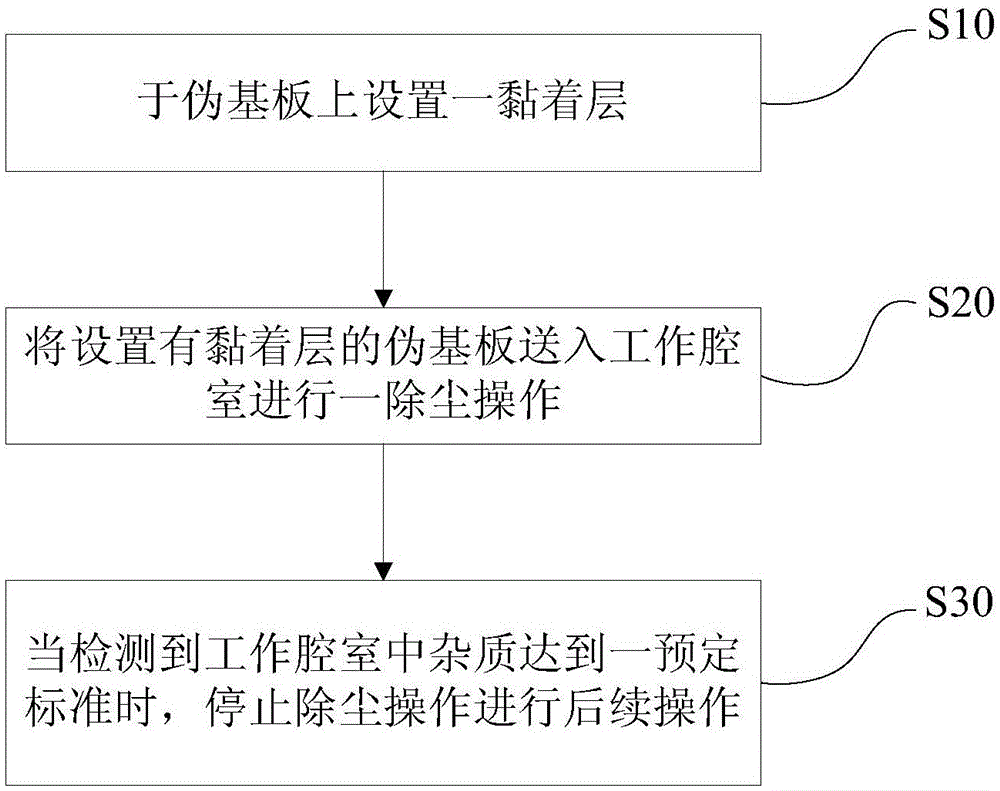
[0038] Such as figure 1 As shown, in one embodiment, the dedusting method of the present invention comprises the following steps:

[0039] S10: disposing an adhesive layer on the dummy substrate;

[0040] S20: sending the dummy substrate provided with the adhesive layer into a working chamber to perform a dust removal operation;

[0041] S30: When it is detected that impurities in the working chamber reach a predetermined standard, stop the dust removal operation and perform subsequent operations.

[0042] In step S10 of this embodiment, a layer of adhesive layer is attac...


PUM


Abstract

The invention discloses a dust removal method. The method includes the following steps that an adhesive layer is arranged on a pseudo substrate; the pseudo substrate provided with the adhesive layer enters a work cavity for dust removal; when it is detected that impurities in the work cavity reach a preset standard, dust removal stops for following operation. The pseudo substrate provided with the adhesive layer on the surface is conveyed into the work cavity, and efficiency of collecting impurities in the work cavity of the pseudo substrate is improved, so dust removal time required before various technical operations is greatly shortened, and work efficiency is improved. Besides, the concentration of impurities in the work cavity can reach the work standard only by conveying a small quantity of pseudo substrates into the work cavity, consumption of the pseudo substrates is effectively reduced, and manufacturing cost is reduced.

Description

technical field [0001] The invention relates to a dust removal method, in particular to a dust removal method for a working chamber for manufacturing a liquid crystal display. Background technique [0002] Liquid Crystal Displays (LCDs) are widely used in various electronic products such as computers, televisions, and mobile phones. The glass substrate of the liquid crystal display is one of the important components of the liquid crystal display. In addition to flatness, the cleanliness of the LCD glass substrate also directly affects the cost and yield of LCD manufacturing. [0003] Manufacturing liquid crystal displays will go through multiple processes such as vapor phase film deposition, exposure, development, etching, etc., and each process is usually carried out in a separate section. Therefore, the glass substrate needs to be transported between the sections of each process. [0004] The above-mentioned vapor phase film deposition, exposure, development, etching an...

Claims


Application Information

Patent Timeline
Patent Type & Authority Applications(China)
IPC IPC(8): B08B7/00
CPCB08B7/0028
Inventor 李仁智林钦茂赖颖辉吴声桢陈政仁余书侨
Owner AU OPTRONICS CORP
Why Eureka
Try Eureka