Multifunctional manual drive wheelchair

A multi-functional and driving technology, which can be used in patient chairs or special transportation tools, vehicle rescue, medical transportation, etc. Low cost and fast effect

Active Publication Date: 2017-11-03
王奋
View PDF6 Cites 0 Cited by
  • Summary
  • Abstract
  • Description
  • Claims
  • Application Information

AI Technical Summary

Problems solved by technology

[0002] Traditional wheelchairs rely on hands to push the wheels so that the wheelchair can move forward. This kind of wheelchair is difficult to use force, and the speed is slow. If the speed is a l

Method used


Image

  • Multifunctional manual drive wheelchair
  • Multifunctional manual drive wheelchair
  • Multifunctional manual drive wheelchair

Examples


Embodiment 1

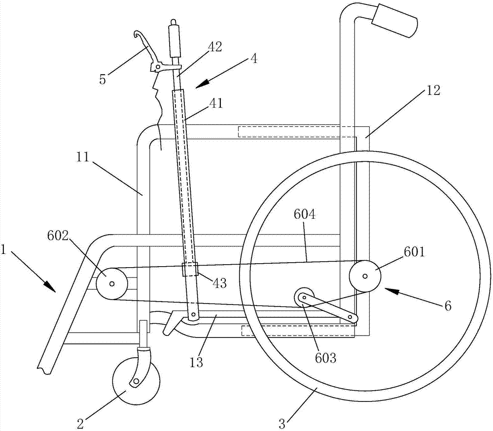
[0031] Such as Figure 1-2 As shown, a multifunctional hand-driven wheelchair provided by the present invention includes a wheelchair body 1, universal wheels 2 rotatably connected to the left and right sides of the front end of the wheelchair body 1, and rotatably connected to the left and right sides of the rear end of the wheelchair body 1. The driving wheel 3, the hand-operated driving device 4 arranged on the left and right sides of the wheelchair body 1, the brake device 5 arranged on the hand-operated driving device 4 and connected to the corresponding side driving wheel 3, and the brake device 5 connected to the corresponding side hand-operated One end of the hand-operated driving device 4 is hinged on the wheelchair body 1 and the other end is in a free state. Since the brake device 5 is a prior art, it will not be described in detail here, and the connection with the drive wheel 3 is not shown in the figure.

[0032] In order to drive the wheelchair forward better, ...

Embodiment 2

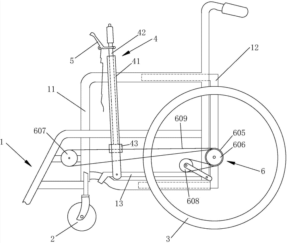
[0040] The difference between embodiment 2 and embodiment 1 is: as image 3 , Figure 4 As shown, the power transmission device 6 includes a bicycle flywheel 2 605 and a bicycle flywheel 3 606 coaxially fixed on the driving wheel 3, a transmission wheel 2 607 rotatably connected to the front end of the wheelchair body 1, and a bicycle flywheel 2 605 and a bicycle flywheel 607. Tensioning wheel 2 608 and transmission chain 2 609 between transmission wheel 2 607, after described transmission chain 2 609 winds clockwise from the lower end of transmission wheel 2 607 to transmission wheel 2 607 upper end, then from the upper end of bicycle flywheel 2 605 Winding clockwise to the lower end, then clockwise from the lower end of the tension wheel 2 608 to the upper end, then counterclockwise from the lower end of the bicycle flywheel 3 606 to the upper end, and finally connected to the lower end of the transmission wheel 2 607, the hand rocker The first 41 is located between the sec...

Embodiment 3

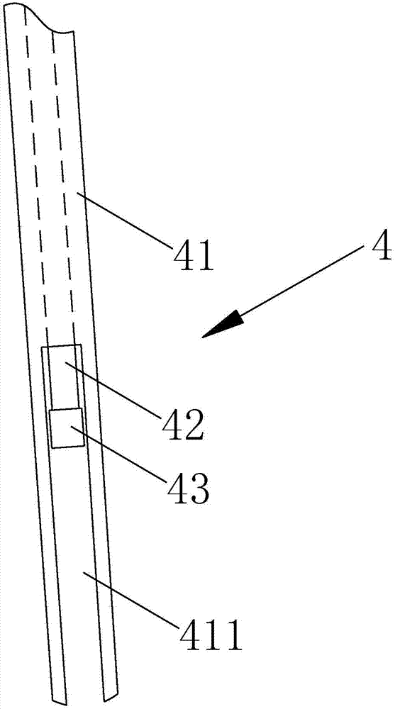
[0043] Such as Figure 5 As shown, the difference between Embodiment 3 and Embodiment 1 is that the power transmission device 6 includes a bicycle flywheel 4 610 coaxially fixed on the driving wheel 3, a transmission chain 3 611, a spring 612, and the hand rocker 1 The middle and lower part of 41 is hinged on the wheelchair body 1 and the hinge point is located above the bicycle flywheel 4 610. One end of the transmission chain 3 611 is fixedly connected to the connecting device 43, and the other end of the transmission chain 3 611 bypasses the bicycle flywheel 4 610 The lower end is fixedly connected with one end of the spring 612, and the other end of the spring 612 is fixedly connected with the hand rocker one 41. The hand-operated driving device 4 in the present embodiment is a horizontal type, and pressing down can drive the wheelchair to move forward, and the pressing down type makes the people on the wheelchair exert more force. The spring 612 is used to automatically ...


PUM


Abstract

The invention relates to the field of wheelchairs, in particular to a multifunctional hand-cranking drive type wheelchair. The multifunctional hand-cranking drive type wheelchair comprises a wheelchair body, universal wheels which are rotatably connected to the left side and the right side of the front end of the wheelchair body, driving wheels which are rotatably connected to the left side and the right side of the rear end of the wheelchair body, hand-cranking type driving devices arranged on the left side and the right side of the wheelchair body, braking devices which are arranged on the hand-cranking type driving devices and connected with the driving wheels on the same sides and power transmission devices which are each connected between the hand-cranking type driving device and the driving wheel on the corresponding side; one end of each hand-cranking type driving device is hinged to the wheelchair body, and the other end of each hand-cranking type driving device is in a free state. According to the wheelchair, the hand-cranking type driving devices arranged on the two sides of the wheelchair can be utilized for driving the wheelchair to move forwards, the braking devices on the hand-cranking type driving devices are utilized for controlling the speed and steering, portability and rapidness are achieved, labor is saved, and the wheelchair further has the advantages that the manufacturing cost is low, the weight is light, the charging problem does not need to be considered, and energy conservation and environment protection are achieved.

Description

technical field [0001] The invention relates to the field of wheelchairs, in particular to a multifunctional hand-driven wheelchair. Background technique [0002] Traditional wheelchairs rely on hands to push the wheels so that the wheelchair can move forward. This kind of wheelchair is difficult to exert force, and the speed is slow. If the speed is slightly faster, no force is needed, and the hands cannot keep up with the speed of the wheels. However, electric wheelchairs are expensive and heavy, and issues such as charging must also be considered. Contents of the invention [0003] The purpose of the present invention is to overcome the above disadvantages and provide a multifunctional hand-driven wheelchair, which can drive the wheelchair forward by using the hand-operated driving devices arranged on both sides of the wheelchair, and use the hand-operated driving devices arranged on the hand-operated driving device The brake device is used to control the speed and ste...

Claims


Application Information

Patent Timeline
IPC IPC(8): A61G5/02A61G5/10
CPCA61G5/023A61G5/025A61G5/1008A61G5/1035
Inventor 王奋王云奇
Owner 王奋
Why Eureka
Try Eureka