Needle head cleaning mechanism

A technology for cleaning mechanisms and needles, which is applied in the direction of spraying devices, coatings, and devices for coating liquid on the surface, etc. It can solve the problems of needle deformation, inability to accurately ensure the position and height of dispensing, product damage, etc., and prevent needle deformation , saving materials and avoiding damage

Active Publication Date: 2016-12-07
BOZHON PRECISION IND TECH CO LTD
View PDF7 Cites 9 Cited by
  • Summary
  • Abstract
  • Description
  • Claims
  • Application Information

AI Technical Summary

Problems solved by technology

[0002] After dispensing the products and parts, it is necessary to clean the needles so that the dispensing needles can be glued out next time. In the prior art, the dispensing needles are generally cleaned manually. The foreign matter on the needle is cleaned. During the tape cleaning process, the needle will be deformed due to manual operation. At the same time, when the needle is deformed and the next dispensing is performed, because the position and height of the needle have also changed, the deformation of the needle will cause The product will be damaged during the next dispensing, and the dispensing position and height cannot be accurately guaranteed

Method used


Image

  • Needle head cleaning mechanism
  • Needle head cleaning mechanism
  • Needle head cleaning mechanism

Examples


Embodiment Construction

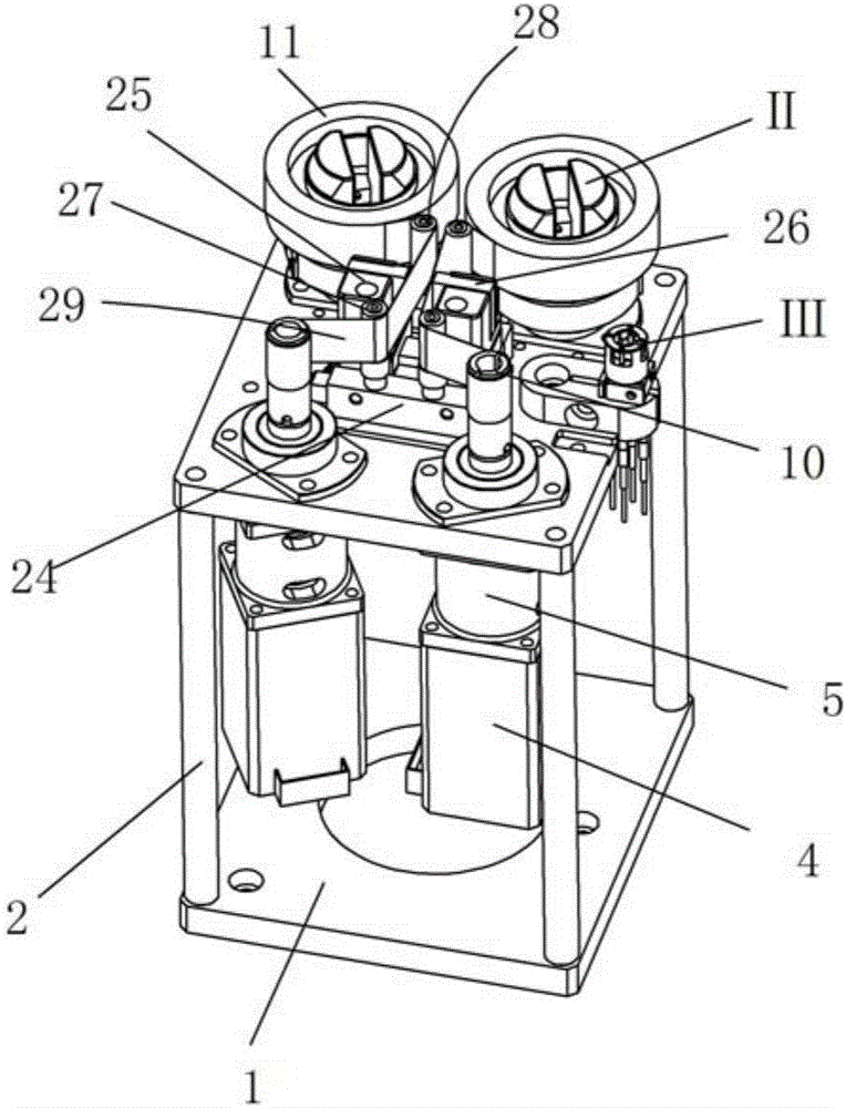
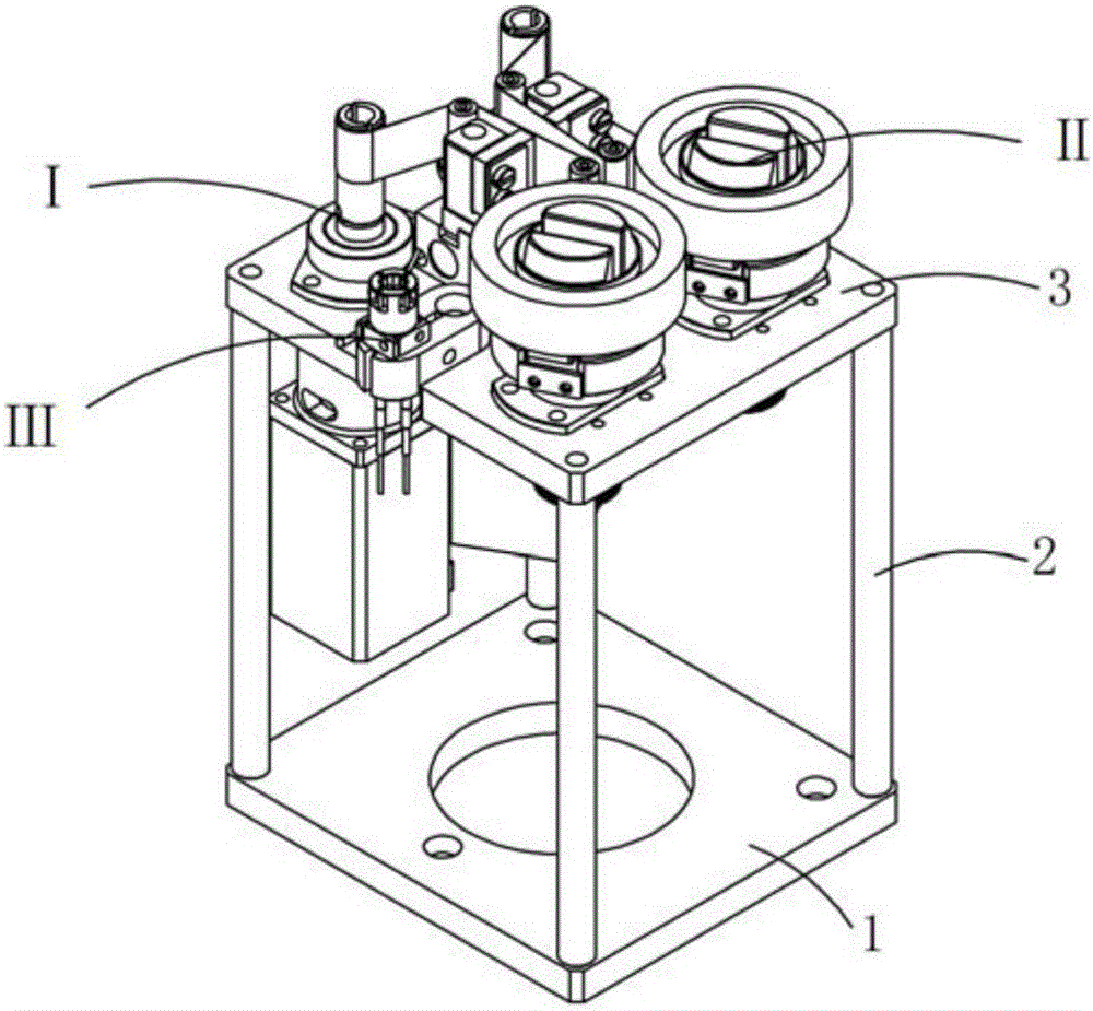
[0030] See attached Figure 1-10 , a needle cleaning mechanism, comprising a base plate 1, on which a mounting plate 3 is installed through support columns 2, there are four sets of support columns, and the four sets of support columns are symmetrically installed at the four corners of the base plate. Both the base plate and the installation plate are of flat plate structure, and the base plate and the installation plate are parallel to each other, and the cross-sectional dimensions of the base plate and the installation plate are the same.

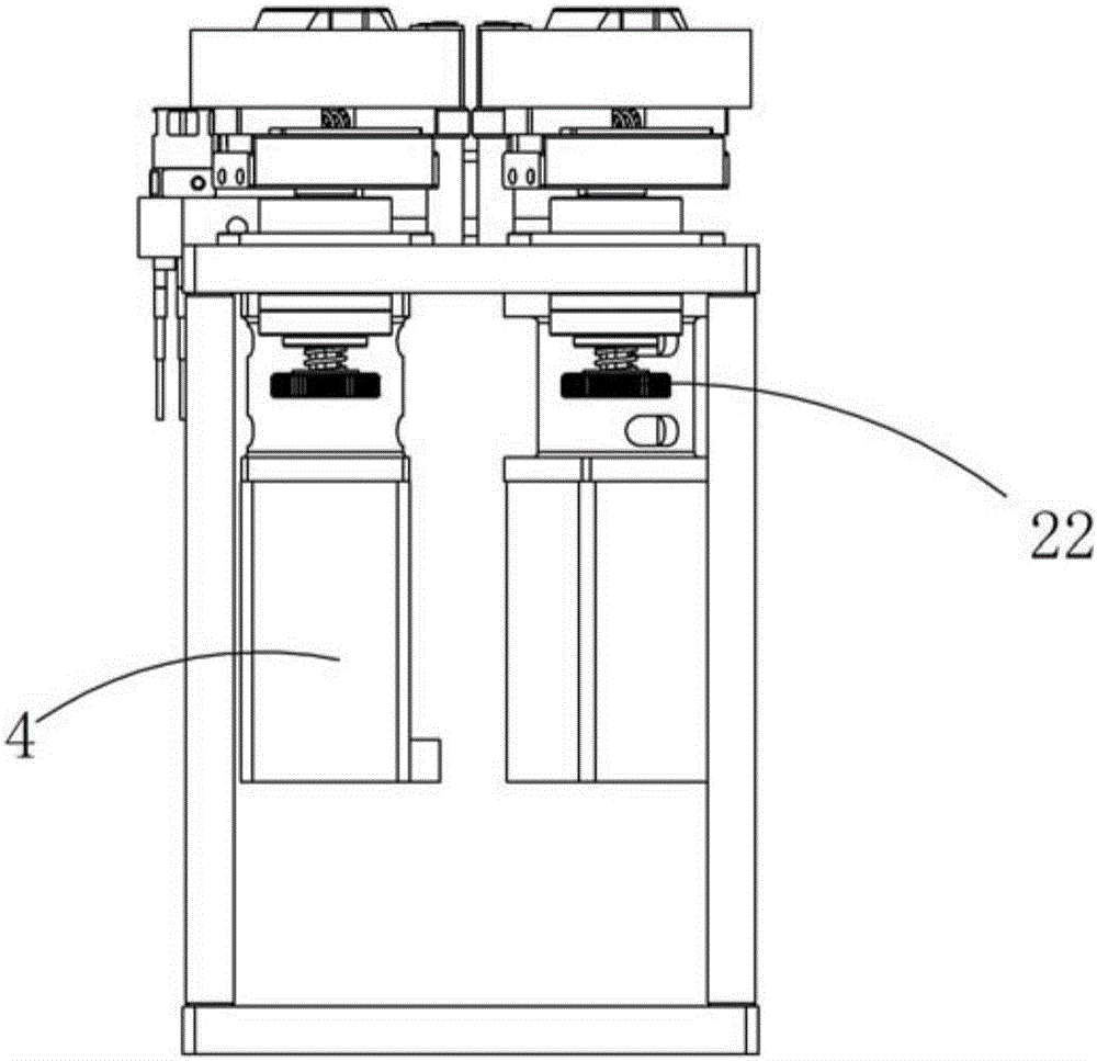
[0031] The left and right sides of the lower part of the mounting plate are respectively equipped with a group of stepping motors 4, two groups of stepping motor mounting plates 5 are installed on the bottom of the mounting plate, and a group of stepping motors are installed on each group of stepping motor mounting plates. , and each set of stepping motors is located between the bottom plate and the mounting plate.

[0032] The main shaf...


PUM


Abstract

The invention relates to a needle head cleaning mechanism. An installing plate is arranged on the bottom plate through supporting columns. A set of stepping motor is arranged on the left side of the lower portion of the installing plate, and a set of stepping motor is arranged on the right side of the lower portion of the installing plate. A material coiling assembly is arranged at the upper end of a spindle of each stepping motor. Rubber belt rolls are arranged on the left side and the right side of the upper portion of the installing plate through rubber belt fixing clamping claw assemblies correspondingly. A clamping claw air cylinder is arranged in the middle of the upper portion of the installing plate. Foam cotton is symmetrically arranged on two clamping claws of the clamping claw air cylinder through foam cotton fixing blocks. A detection assembly capable of detecting the position and the height of a needle head is arranged at the upper portion of the installing plate. Two sets of front wheels and two sets of rear wheels are arranged at the upper portion of the clamping claw air cylinder, and the foam cotton is located between the corresponding front wheels and the corresponding rear wheels. A rubber belt on each set of rubber belt roll sequentially passes the corresponding rear wheels, the corresponding foam cotton and the corresponding front wheels and is bonded to the corresponding material coiling assembly. The clamping claw air cylinder drives the foam cotton to move, the two foam cotton sets clamp the needle head, the needle head is slowly drawn out upwards, and the rubber belts between the two foam cotton sets clean away foreign matter on the needle head at the same time.

Description

Technical field: [0001] The invention relates to the field of cleaning mechanism equipment, and more specifically relates to a needle cleaning mechanism that realizes regular cleaning of dispensing needles and precise positioning of the position and height of the needles. Background technique: [0002] After dispensing the products and parts, it is necessary to clean the needles so that the dispensing needles can be glued out next time. In the prior art, the dispensing needles are generally cleaned manually. The foreign matter on the needle is cleaned. During the tape cleaning process, the needle will be deformed due to manual operation. At the same time, when the needle is deformed and the next dispensing is performed, because the position and height of the needle have also changed, the deformation of the needle will cause The damage to the product during the next dispensing cannot accurately guarantee the dispensing position and height. Invention content: [0003] The o...

Claims


Application Information

Patent Timeline
Patent Type & Authority Applications(China)
IPC IPC(8): B05C5/02B05B15/02
CPCB05C5/02
Inventor 吕绍林马金勇朱晓锋刘武雷
Owner BOZHON PRECISION IND TECH CO LTD
Why Eureka
Try Eureka