Method for improving weld microstructure of Al/Cu friction stir welding in follow-up manner

A friction stir welding, follow-up technology, applied in the field of forging and metallurgy, can solve the problems of weld defects, low heat input, influence of electrical conductivity, etc., to remove holes and tunnel defects, enhance use adaptability, device structure simple effect

Active Publication Date: 2016-12-07
山东因泽智能设备有限公司
View PDF6 Cites 14 Cited by
  • Summary
  • Abstract
  • Description
  • Claims
  • Application Information

AI Technical Summary

Benefits of technology

This new technology allows for better control over how well two materials are joined together during brazing processes by controllably reducing pressure on them while they're being worked through. By doing this, cracks or imperfections caused from thermal shock will become less visible when compared to traditional methods like resistance spot welded joints. Additionally, these improvements improve the overall quality of the resulting product due to improved strength and electric conduction. Overall, this innovation provides technical benefits such as enhanced performance and reduced costs associated therewith.

Problems solved by technology

The technical problem addressed in this patents relates to improving the quality and efficiency of joining different materials together without causing damage or forming voids called “defects” (nugs) caused by current methods like arc weldings. This issue arises from differences between specific material's melting temperatures and their respective crystal structures. Existing techniques have limitations with regards to reducing these issues while maintaining good physical strength and electric conduction rates.

Method used


Image

  • Method for improving weld microstructure of Al/Cu friction stir welding in follow-up manner
  • Method for improving weld microstructure of Al/Cu friction stir welding in follow-up manner
  • Method for improving weld microstructure of Al/Cu friction stir welding in follow-up manner

Examples


Embodiment Construction

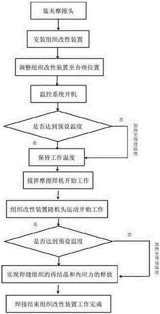
[0013] Such as figure 1 Shown, the present invention is the method that follow-up type improves Al / Cu friction stir welding weld seam structure, and its steps are:

[0014] (1) Step 1: Adjust the minimum working pressure and adjust the minimum pressing force of the tissue modification mechanism;

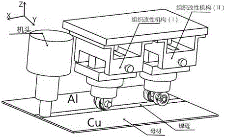
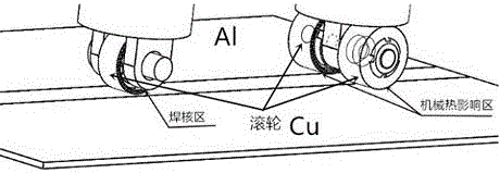
[0015] (2) Step 2: Use the control mechanism to adjust the position of the tissue modification mechanism. In the structure modification mechanism I with a single roller, the roller covers the entire weld nugget area and a part of the mechanical heat-affected zone; in the structure modification mechanism II with two rollers, two The two rollers correspond to the entire mechanical heat-affected zone on the Al / Cu side and a part of the heat-affected zone of the weld and the nugget zone;

[0016] (3) Step 3: Turn on the temperature control system, set the modification temperature, set the roller temperature T1=290~315℃ in the tissue modification mechanism I; preset the Al side roller te...


PUM


Abstract

The invention discloses a method for improving a weld microstructure of Al/Cu friction stir welding in a follow-up manner. The method comprises the following steps: (1) adjusting the lowest working pressure, and adjusting the lowest pressing amounts of microstructure modification mechanisms; (2) adjusting the positions of the microstructure modification mechanisms by virtue of an adjustment-control mechanism, wherein two rolling wheels in a microstructure modification mechanism (II) with double rolling wheels correspond to the whole thermo-mechanical affected zone at an Al/Cu side as well as a part of a weld heat-affected zone and a part of a weld nugget zone; (3) starting up temperature control systems of the microstructure modification mechanisms, setting a modification temperature, setting a temperature T1 of the rolling wheels of a microstructure modification mechanism (I) to 290-315 DEG C, presetting a temperature T2 of the rolling wheels at an Al side of the microstructure modification mechanism (II) to 275-290 DEG C, setting a temperature T3 of the rolling wheels at a Cu side to 480-510 DEG C, heating the three rolling wheels to the modification temperature and then stopping heating; and (4) starting up a friction stir welding machine to start welding, enabling the microstructure modification mechanisms to start to work, and ensuring that the modification temperature set in the step (3) is achieved and stabilized until weld modification is ended during working by virtue of the temperature control systems of the microstructure modification mechanisms, wherein modification for the microstructure of the heat-affected zone can be realized after the end of the welding.

Description


Claims


Application Information

Patent Timeline
Owner 山东因泽智能设备有限公司
Why Eureka
Try Eureka