
Pneumatic tire

A pneumatic tire and tire technology, applied in tire parts, tire tread/tread pattern, transportation and packaging, etc., can solve the problems of reduced tread rigidity and poor handling stability, and improve wet performance. , Improve the effect of handling stability performance

Active Publication Date: 2016-12-07
SUMITOMO RUBBER IND LTD
View PDF6 Cites 8 Cited by
  • Summary
  • Abstract
  • Description
  • Claims
  • Application Information

AI Technical Summary

Problems solved by technology

[0003] However, the above-mentioned pneumatic tires have problems such as reduced rigidity of the tread portion and poor steering stability.

Method used


Image

  • Pneumatic tire
  • Pneumatic tire
  • Pneumatic tire

Examples


Embodiment

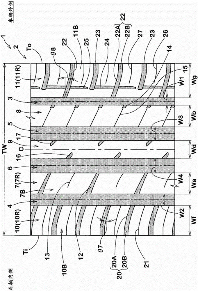
[0075] Prototyped according to the specifications in Table 1 with figure 1 Pneumatic tires for passenger cars with the basic pattern and the size of 205 / 55R16, and the handling stability and wet road performance were tested. The main common specifications and test methods of each test tire are as follows.

[0076] Tread contact width TW: 158mm

[0077] Groove depth of outer shoulder main groove: 7.8mm

[0078] Groove depth of inner shoulder main groove: 7.8mm

[0079] Groove Depth of Outer Central Main Groove: 8.0mm

[0080] Groove Depth of Medial Central Main Groove: 8.0mm

[0081] Groove depth of medial middle transverse groove: 3.4mm~6.3mm

[0082] The groove depth of the outer middle horizontal groove: 6.3mm

[0083]

[0084] Under the following conditions, the lateral resistance force was measured for each test tire using an indoor tester, and the lateral rigidity was obtained. The results are expressed by means of an index with the value of Example 1 being 100. ...


PUM


Abstract

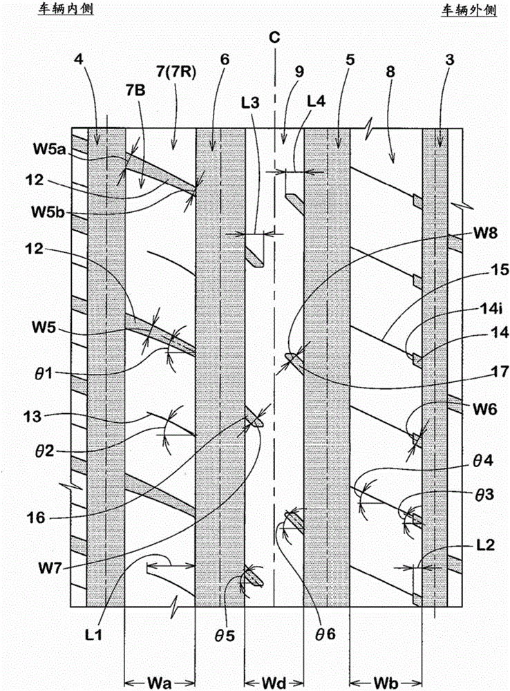
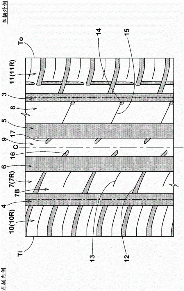
A pneumatic tire (1) has a tread pattern capable of improving wet performance and steering stability in a well balanced manner. An inboard middle land portion (7) is provided with inboard middle axial grooves (12) connecting between an inboard shoulder main groove (4) and an inboard crown main groove (6) and inclined at 20 to 30 degrees. An outboard middle land portion (8) is provided with outboard middle semi-blind grooves (14) extending axially inwardly from a outboard shoulder main groove (3), and outboard middle sipes (15) extending from the axially inner ends of the outboard middle semi-blind grooves (14) to the outboard crown main groove (5). The outboard middle semi-blind grooves (14) and the outboard middle sipes (15) are inclined at 20 to 30 degrees. A center land portion (9) is provided with inboard crown semi-blind grooves (16) extending from the inboard crown main groove (6), and outboard crown semi-blind grooves (17) extending from the outboard crown main groove (5).

Description

technical field [0001] The present invention relates to a pneumatic tire having improved wet performance and handling stability in a balanced manner. Background technique [0002] In recent years, a pneumatic tire having excellent wet performance and handling stability has been desired. In order to improve the wet performance of pneumatic tires, for example, it has been proposed to provide main grooves and lateral grooves having large groove volumes in the tread portion thereof. [0003] However, the above-mentioned pneumatic tires have problems such as reduced rigidity of the tread portion and poor steering stability. [0004] Patent Document 1: Japanese Patent Laid-Open No. 2013-100020 Contents of the invention [0005] The present invention has been made in view of the above problems, and its main purpose is to provide a method based on improving the grooves and sipes provided on the inner middle land portion, the outer middle land portion, and the center land portion...

Claims


Application Information

Patent Timeline
Patent Type & Authority Applications(China)
IPC IPC(8): B60C11/04B60C11/11
CPCB60C2011/0383B60C2011/0381B60C2011/0372B60C2011/0353B60C11/0306B60C2011/0365B60C11/0304B60C2011/0388B60C11/0311B60C11/04B60C11/12
Inventor 末野顺也
Owner SUMITOMO RUBBER IND LTD
Learn More