Automatic lifting-carrying device for building retaining wall

A technology of automatic lifting and handling device, applied in the direction of lifting device, construction, lifting frame, etc., can solve the problems of slow handling speed, low construction efficiency, low work efficiency, etc., and achieve fast handling speed, high construction efficiency, and high work efficiency. Effect

Active Publication Date: 2016-12-07
成武盛阳热力有限公司
View PDF8 Cites 11 Cited by
  • Summary
  • Abstract
  • Description
  • Claims
  • Application Information

AI Technical Summary

Problems solved by technology

[0003] In order to solve the above problems, the present invention provides an automatic lifting and conveying device for building retaining walls, which can solve the problems of manual stacking of existing retaining walls, the need for manual full-process operation, low construction efficiency, serious safety hazards, and the need for manual up and down transportation. , slow handling speed and low work efficiency, etc., can realize the stable automatic lifting and handling function of the retaining wall, high construction efficiency, no safety hazards, and has the advantages of automatic lifting and handling, fast handling speed and high work efficiency

Method used


Image

  • Automatic lifting-carrying device for building retaining wall
  • Automatic lifting-carrying device for building retaining wall
  • Automatic lifting-carrying device for building retaining wall

Examples


Embodiment Construction

[0015] In order to make the technical means, creative features, goals and effects achieved by the present invention easy to understand, the present invention will be further described below in conjunction with specific illustrations.

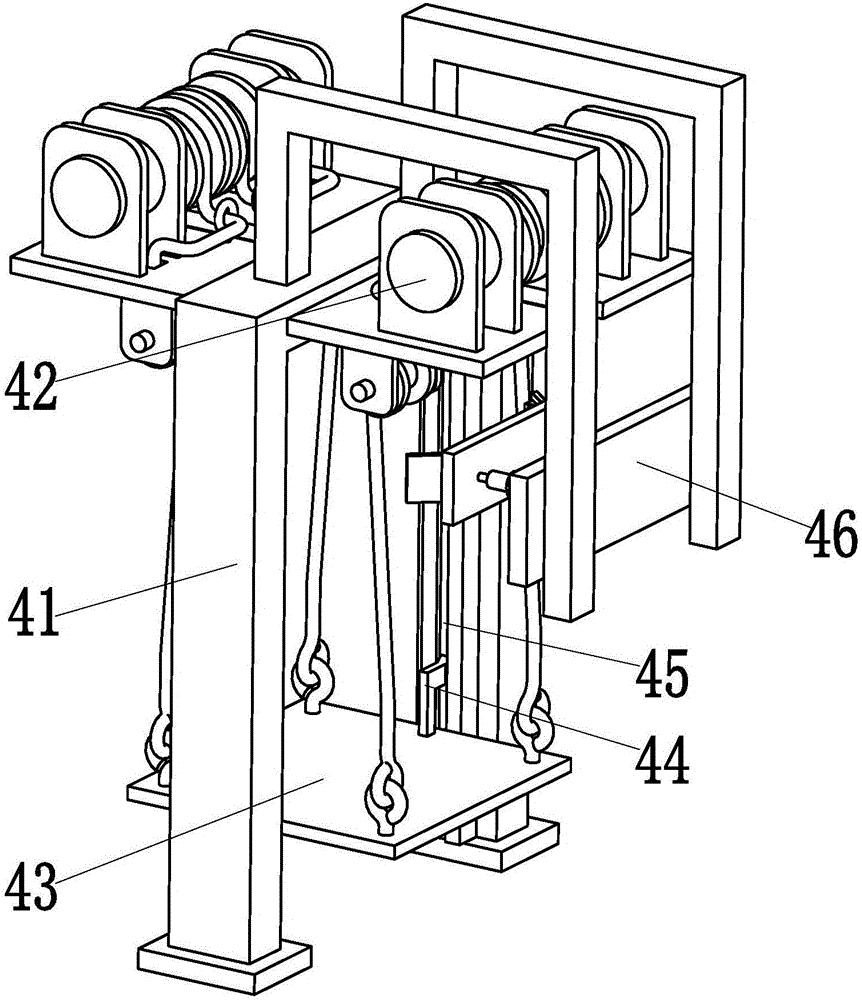
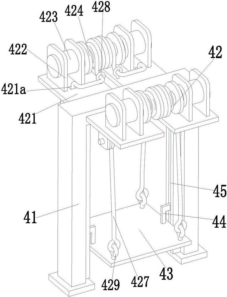
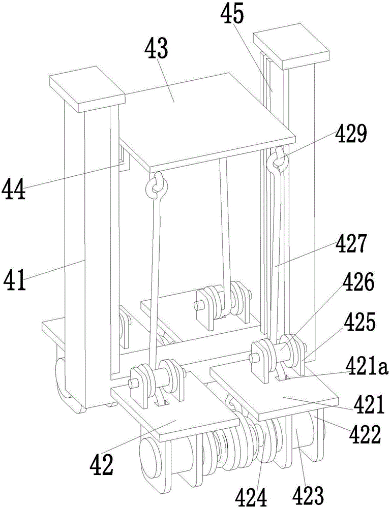
[0016] Such as Figure 1 to Figure 5 As shown, an automatic lifting and handling device for a building retaining wall includes a concave bracket 41, four lifting branch chains 42 are symmetrically arranged on both sides of the upper end surface of the concave bracket 41, and lifting plates 43 are installed on the lower ends of the four lifting branch chains 42. , the masonry grabbed by the operator is placed on the lifting plate 43, and two limit sliding posts 44 are welded symmetrically on both sides of the upper end surface of the lifting plate 43. They are connected by sliding fit, and the two limit chute 45 are respectively welded on the inner walls of both sides of the concave bracket 41. Lifting plate 43 can do stable lifting and carrying...


PUM


Abstract

The invention relates to an automatic lifting-carrying device for a building retaining wall. The automatic lifting-carrying device comprises a concave support, wherein four lifting branched chains are symmetrically arranged at the two sides of the upper end surface of the concave support; a lifting plate is installed at the lower ends of the four lifting branched chains; two limit slide columns are symmetrically welded at the two sides of the upper end surface of the lifting plate; the two limit slide columns are connected with two limit slide grooves in a manner of slide fit respectively; the two limit slide grooves are welded in the inner walls of the two sides of the concave support respectively; the lifting plate is capable of carrying out a stable lifting-carrying motion under the driving of the four lifting branched chains through the limit-support action of the two limit slide columns and the two limit slide grooves; and a pushing-placing mechanism is welded at the upper end of the concave support, and the lifted-carried grouted rubbles are automatically pushed onto the retaining wall through the pushing-placing mechanism. The automatic lifting-carrying device disclosed by the invention is capable of realizing a stable automatic lifting-carrying function for the retaining wall, and provides a new way of automatic and rapid lifting-carrying for the retaining wall.

Description

technical field [0001] The invention relates to the technical field of geotechnical engineering, in particular to an automatic lifting and conveying device for building retaining walls. Background technique [0002] There are generally retaining walls on both sides of the expressway section and the urban highway section near the mountain. The types of retaining walls are divided into two types: masonry retaining walls and concrete retaining walls. The main functions of the retaining walls are: 1. Support roadbed filling or hillside soil; 2. Prevent filling or soil deformation and instability; 3. Prevent landslides and landslides, so retaining walls play a vital role in road safety; The earth walls are all set up next to the mountain, and the raw materials for masonry masonry are abundant, so the masonry masonry retaining wall is mainly used. The grouted masonry is manually grabbed and placed in the transport trolley, the operator pushes the trolley to the conveying equipmen...

Claims


Application Information

Patent Timeline
Patent Type & Authority Applications(China)
IPC IPC(8): B66F7/02B66F7/28B65G47/82E02D29/02
CPCB65G47/82B66F7/02B66F7/28E02D29/02E02D29/0266
Inventor 詹晨
Owner 成武盛阳热力有限公司
Why Eureka
Try Eureka