A kind of retaining wall forming equipment for asphalt concrete highway

A technology of asphalt concrete and forming equipment, which is applied in the field of geotechnical engineering, can solve the problems of hidden dangers of masonry rolling, manual up and down handling, and low work efficiency, and achieve high construction efficiency, good tensioning effect, and high work efficiency. Effect

Inactive Publication Date: 2018-02-06
江苏山推工程机械有限公司
View PDF7 Cites 0 Cited by
  • Summary
  • Abstract
  • Description
  • Claims
  • Application Information

AI Technical Summary

Problems solved by technology

[0003] In order to solve the above problems, the present invention provides a retaining wall forming equipment for asphalt concrete roads, which can solve the problems of the existing manual stacking method of retaining walls, the need for manual full-process operation, low construction efficiency, serious safety hazards, and transportation problems. There are no left and right limits in the process, which is prone to hidden dangers of masonry rolling, poor conveying effect, manual up and down handling, slow handling speed, and low work efficiency. The automatic forming function of the retaining wall can be realized, and the construction efficiency is high. Potential safety hazards, the left and right limits are carried out throughout the conveying process, which eliminates the hidden danger of rolling during the masonry conveying process, and has the advantages of automatic lifting and conveying, fast conveying speed and high work efficiency, and provides an automatic and fast retaining wall. new ways to shape

Method used


Image

  • A kind of retaining wall forming equipment for asphalt concrete highway
  • A kind of retaining wall forming equipment for asphalt concrete highway
  • A kind of retaining wall forming equipment for asphalt concrete highway

Examples


Embodiment Construction

[0023] In order to make the technical means, creative features, goals and effects achieved by the present invention easy to understand, the present invention will be further described below in conjunction with specific illustrations.

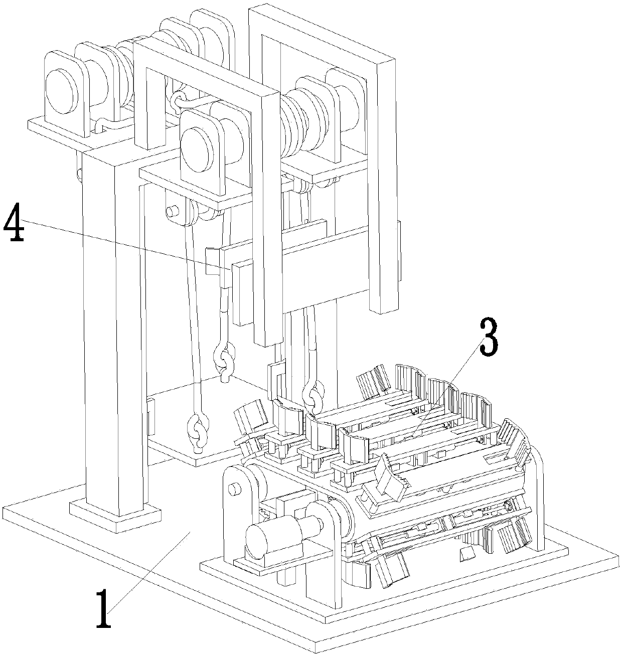
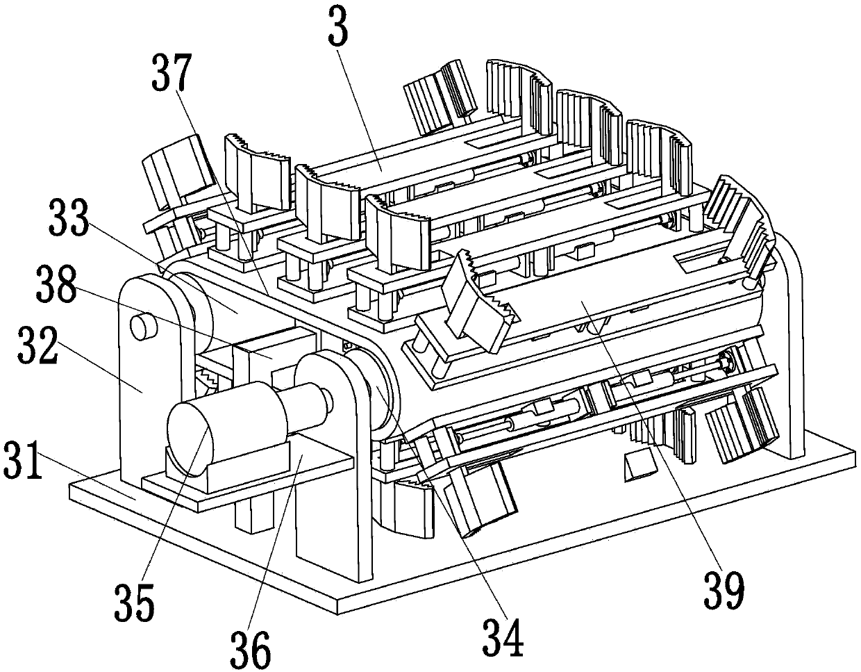
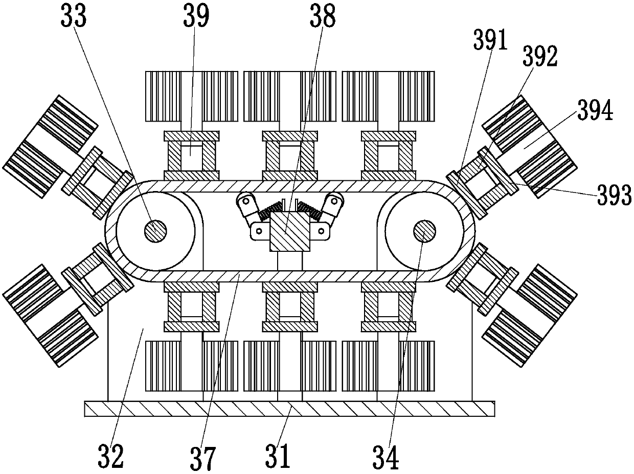
[0024] Such as Figure 1 to Figure 10 As shown, a retaining wall forming equipment for asphalt concrete roads includes a base 1, and a limited delivery device 3 is installed on the right side of the upper end surface of the base 1. Limit conveying function, there are left and right limit during the whole conveying process of masonry, which eliminates the hidden danger of rolling down in the conveying process of masonry, the conveying effect is good, no manual operation is required, and the upper end surface of the base 1 is installed on the left side The push-and-release device 4, the lifting push-and-release device 4 can realize the automatic lifting and conveying function to the masonry, without the need for manual up and down conveyance, with...


PUM


Abstract

The invention relates to retaining wall forming equipment for a bituminous concrete road. The retaining wall forming equipment comprises a base, wherein a limiting conveying device is mounted on the right side of the upper end surface of the base, and can realize a stable limiting conveying function for masonry; left and right limitations for the masonry in the whole conveying process are realized, so that the potential fall-off hazard in the masonry conveying process is eliminated, the conveying effect is good, and no manual operation is needed; a lifting and pushing device is mounted on the left side of the upper end surface of the base, and can realize an automatic lifting and carrying function for the masonry, so that workers, carrying the masonry, do not need to climb up and down, the carrying speed is high, and the working efficiency is high; the limiting conveying device comprises a conveying base plate welded on the upper end surface of the base; four conveying lugs are symmetrically welded on the upper end surface of the conveying base plate; and a driven roller is mounted between the two conveying lugs located on the left side of the conveying base plate through bearings. The retaining wall forming equipment can realize an automatic retaining wall forming function, and a new way for automatic and quick forming of a retaining wall is provided.

Description

technical field [0001] The invention relates to the technical field of geotechnical engineering, in particular to a retaining wall forming device for asphalt concrete roads. Background technique [0002] There are generally retaining walls on both sides of the asphalt concrete road section near the mountain. The types of retaining walls are divided into two types: masonry retaining walls and concrete retaining walls. The main functions of the retaining walls are: 1. Support Subgrade filling or hillside soil; 2. Prevent filling or soil deformation and instability; 3. Prevent landslides and landslides, so retaining walls play a vital role in road safety; It is located next to the mountain, and the raw materials of masonry are abundant, so the masonry retaining wall is mainly used. The existing masonry retaining wall is mainly built by manual methods. First, the processed masonry is artificially Grab and place it in the transport trolley, the operator pushes the transport trol...

Claims


Application Information

Patent Timeline
Patent Type & Authority Patents(China)
IPC IPC(8): E02D29/02
CPCE02D29/0283
Inventor 杜朝辉高攀郭峰江国清
Owner 江苏山推工程机械有限公司
Why Eureka
Try Eureka