Wire winding machine

A stranding machine and stranding technology, applied in the manufacture of electrical components, circuits, cables/conductors, etc., can solve the problems of bulky stranding machines, inconvenient operation, increased equipment costs, etc. Good stability and the effect of increasing the number of wire racks

Inactive Publication Date: 2009-02-04
CHANGZHOU HENGFENG SPECIAL CONDUCTOR CO LTD
View PDF2 Cites 34 Cited by
  • Summary
  • Abstract
  • Description
  • Claims
  • Application Information

AI Technical Summary

Problems solved by technology

Enlarging the diameter of the winch will make the entire stranding machine bulky, inconvenient to operate, and also increase the cost of equipment; while reducing the distance between the wire racks will easily lead to mutual interference between the wires, causing confusion

Method used


Image

  • Wire winding machine

Examples


Embodiment Construction

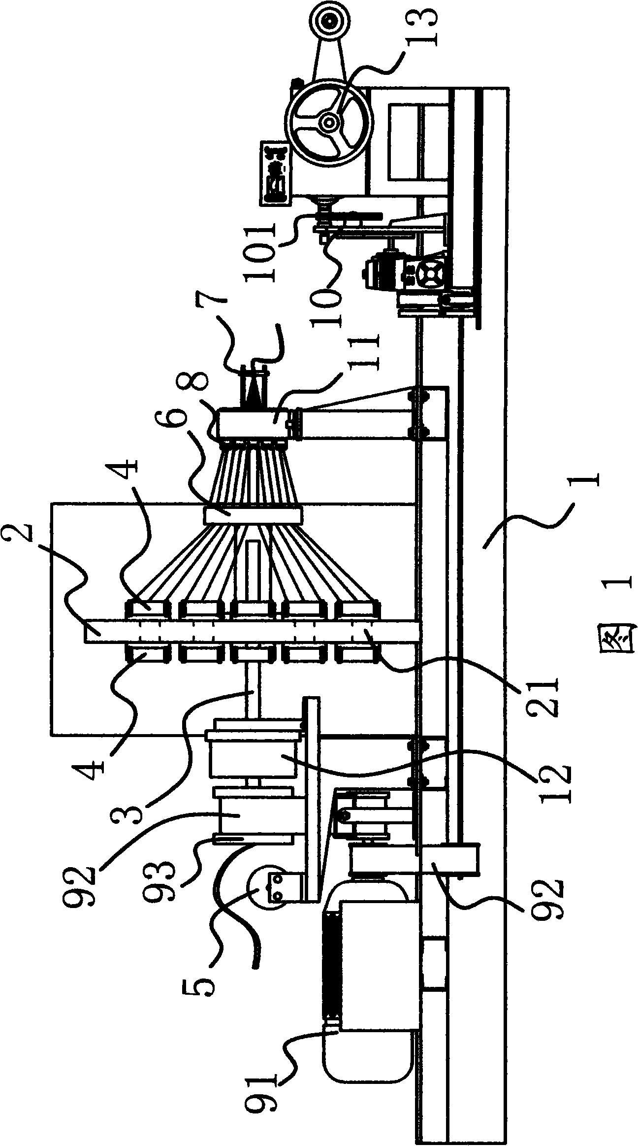
[0020] As shown in FIG. 1 , the stranding machine includes a frame 1, a wire reel plate 2 arranged on the frame 1, and a rotating shaft 3 that can rotate relative to the frame 1 is fixed in the center of the wire installation plate 2. The One end of the rotating shaft 3 is connected with the driving mechanism, and the other end is rotatably connected with the twisted wire seat 11 on the frame 1 . One end of the above-mentioned rotating shaft 3 passes through the stranded wire seat 11 and a stranded wire eye mold 7 is installed at the end of the rotating shaft 3 . A wire take-up device fixed on the frame 1 is provided on the side of the wire reel plate 2 . The wire take-up device includes a wire take-up reel 13 fixed on the frame 1 . A wire baffle 6 fixed on the rotating shaft 3 is provided between the wire reel plate 2 and the wire take-up device. The stranding eye mold 7 , the stranding seat 11 , and the wire baffle 6 are located on the same side of the wiring reel plate 2 ...


PUM


Abstract

The invention relates to a wire strander which is particularly applicable for cable production. The strander comprises a frame and a wiring disc arranged on the frame. A rotating shaft which can rotate relatively with respect to the frame is fixed at the center of the wiring disc and is connected with a drive mechanism. A take-up device fixed on the frame is installed at the side of the wiring disc. The strander is characterized in that a plurality of coil holders are installed at two sides of the wiring disc; the heads of the wire coils on the coil holders at one side of the wiring disc can run through the wiring disc and reach the other side of the wiring disc. Compared with prior art, the strander has the advantages that: 1, the coil holders are reasonable in arrangement, thus increasing the number of the coil holders; the whole structure is compact in structure and low in cost and is easy to operate; 2, the feed pitch can be flexibly adjusted according to needs and the wires arranged on the strander will not be mixed up, so work stability is good and efficiency is high; 3, the feed pitch can be adjusted according to needs, so various products with different specifications can be produced, thereby the wire strander is widely applicable.

Description

technical field [0001] The invention relates to the technical field of machinery, in particular to a stranding machine, which is especially suitable for producing cables. Background technique [0002] In order to improve the stranding machine, people have carried out long-term exploration and proposed various implementation schemes. For example, the Chinese patent document discloses a cabling reel winch 200420024471.8, which includes a ring-shaped pressure plate, a fork-shaped frame is fixed on the pressure-bearing plate, and one end of the fork head of the fork frame is connected with an empty tubular The main shaft, the main shaft is located at the port on the side of the fork frame, and a guide roller group for guiding the movement of the cable is provided on the fork frame. There is a cable arrangement device, and the bottom of the pressure plate is provided with a supporting wheel. Another person has applied for a patent named frame winch twister application number: 2...

Claims


Application Information

Patent Timeline
Patent Type & Authority Applications(China)
IPC IPC(8): H01B13/02
Inventor 何如森
Owner CHANGZHOU HENGFENG SPECIAL CONDUCTOR CO LTD
Why Eureka
Try Eureka