An in-situ shearing device and installation method for obtaining rock and soil strength parameters

A shearing device, a technology of rock and soil mass, applied in the direction of measuring device, strength characteristics, testing material strength by applying a stable shearing force, etc., can solve the unbalanced force of shearing ring, test failure, insufficient normal pressure and other problems to achieve the effect of solving adverse effects, convenient assembly and disassembly, and high work efficiency

Active Publication Date: 2018-10-16
CENT SOUTHERN CHINA ELECTRIC POWER DESIGN INST CHINA POWER ENG CONSULTING GROUP CORP +2
View PDF6 Cites 0 Cited by
  • Summary
  • Abstract
  • Description
  • Claims
  • Application Information

AI Technical Summary

Problems solved by technology

[0004] (1) The normal pressure is insufficient, and heavy objects are directly stacked on the surface of the sample. The weight that can be stacked is limited, and it is easy to lose stability during the shearing process, which will easily lead to test failure.
[0005] (2) In order to solve the problem in (1), the researchers used backloading back pressure combined with jack force transmission to provide normal pressure, and installed a roller row between the top of the sample and the jack. Under the action of high normal pressure, The rolling resistance of the roller row can have a large impact on the shear load data
[0006] (3) At present, the in-situ shear tests on the site use the rear edge excavation surface as the reaction force support of the horizontal load. When the high normal pressure acts, the rear edge support is prone to premature failure and the test fails
[0007] (4) It is not easy to set shear joints in a single shear ring. Even if the shear joints are reserved, the shear joints will be narrowed due to the downward movement of the shear ring due to the compression of the soil during the normal loading process.
[0008] (5) The force of the single shear ring is easy to be eccentric, and the thrust position is close to the shear surface during shearing. The unbalanced force of the shear ring is prone to eccentricity, and excessive torque is generated on the force surface
[0009] The results obtained by using the existing in-situ shearing device will have a certain impact on the test data. In order to truly and effectively obtain the shear mechanical strength parameters of coarse-grained soil, it is urgent to improve the existing in-situ shearing device.

Method used


Image

  • An in-situ shearing device and installation method for obtaining rock and soil strength parameters
  • An in-situ shearing device and installation method for obtaining rock and soil strength parameters
  • An in-situ shearing device and installation method for obtaining rock and soil strength parameters

Examples


Embodiment Construction

[0058] The implementation of the present invention will be described in detail below in conjunction with the accompanying drawings, but they do not constitute a limitation to the present invention, they are only examples, and the advantages of the present invention will become clearer and easier to understand.

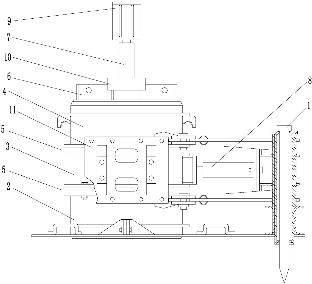
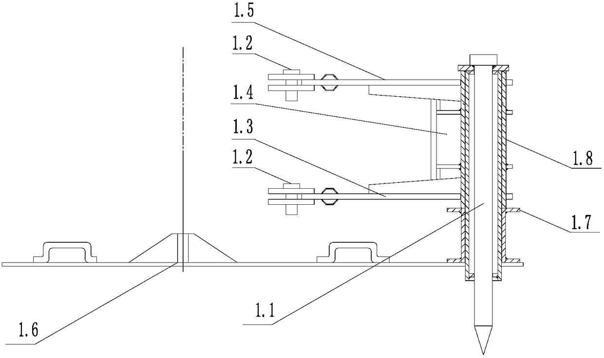
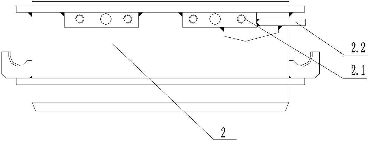
[0059] refer to Figure 1-12 Described: the present invention is an in-situ shearing device and installation method for obtaining rock and soil strength parameters, which is characterized in that: a slotted lining tile 5 is placed between the circular upper ring 4, the middle ring 3 and the lower ring 2, Side guide rails 11 are installed on both sides of the upper ring 4 and the lower ring 2, a ring bolster 6 is installed on the upper end of the upper ring 4, and a ball is installed on the ring bolster 6. Head 10, a vertical jack 7 is installed on the ball head 10, and a small beam 9 is installed on the top of the vertical jack 7; a horizontal jack 8 is arranged direct...


PUM

PropertyMeasurementUnit
thicknessaaaaaaaaaa
thicknessaaaaaaaaaa
diameteraaaaaaaaaa

Abstract

The invention discloses an in-situ shearing device capable of acquiring strength parameters of a rock-soil body and a mounting method. The in-situ shearing device is characterized in that seam lining tiles (5) are placed among a round upper ring (4), a round middle ring (3) and a round lower ring (2), side guide rails (11) are mounted on two sides of each of the upper ring (4) and the lower ring (2), a ring upper bolster (6) is mounted at the upper end of the upper ring (4), a bulb (10) is mounted on the ring upper bolster (6), a vertical jack (7) is mounted on the bulb (10), and a small beam (9) is mounted at the top of the vertical jack (7); a horizontal jack (8) and a load transferring support (1) are mounted in a matched manner. The defects that a single shearing ring in the prior art is easily eccentric under stress, the thrust position approaches the shearing surface during shearing and the shearing ring is easily eccentric because of unbalanced stress are overcome, and the in-situ shearing device has the advantages of being detachable, higher in working efficiency and suitable for outdoor experiments.

Description

technical field [0001] The invention belongs to an in-situ shearing experiment device for rock and soil, and more specifically relates to an in-situ shearing device and an installation method for obtaining strength parameters of a rock and soil mass. Background technique [0002] For coarse-grained soils containing oversize particles, the in-situ shear test is undoubtedly the most pertinent method for obtaining evidence of mechanical parameters, and a certain number of typical sites are directly selected on the project site for on-site tests. Avoid the influence of soil sample agitation during sample acquisition and handling. [0003] However, the current in-situ shear test of rock and soil uses a single shear ring, and there are the following problems in the test process: [0004] (1) The normal pressure is insufficient, and heavy objects are directly stacked on the surface of the sample. The weight that can be stacked is limited, and it is easy to lose stability during th...

Claims


Application Information

Patent Timeline
Patent Type & Authority Patents(China)
IPC IPC(8): G01N3/24
CPCG01N3/24G01N2203/0025
Inventor 龚辉尚思良徐炎兵张晓健艾传井杨治平王伟胡矾张明峻魏小龙夏浩
Owner CENT SOUTHERN CHINA ELECTRIC POWER DESIGN INST CHINA POWER ENG CONSULTING GROUP CORP
Why Eureka
Try Eureka