IGBT junction temperature measuring device

A technology of measuring devices and pins, applied in the direction of measuring devices, measuring electricity, measuring electrical variables, etc.

Inactive Publication Date: 2016-12-07
INST OF ELECTRICAL ENG CHINESE ACAD OF SCI
View PDF6 Cites 24 Cited by
  • Summary
  • Abstract
  • Description
  • Claims
  • Application Information

AI Technical Summary

Problems solved by technology

[0008] The purpose of the present invention is to overcome the shortcoming of existing IGBT jun

Method used


Image

  • IGBT junction temperature measuring device
  • IGBT junction temperature measuring device
  • IGBT junction temperature measuring device

Examples


Embodiment Construction

[0043] The present invention will be further described below in conjunction with the accompanying drawings and specific embodiments.

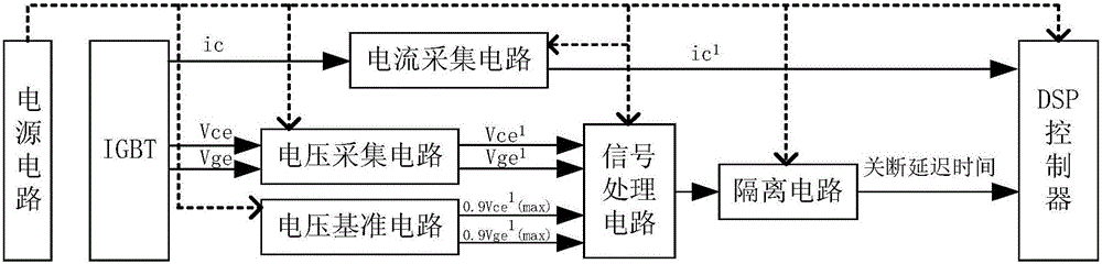
[0044] figure 1 Shown is the block diagram of the circuit structure of the IGBT junction temperature measuring device of the present invention. Such as figure 1 As shown, the IGBT junction temperature measuring device of the present invention includes a power supply circuit, a DSP controller, a voltage acquisition circuit, a current acquisition circuit, a voltage reference circuit, a signal processing circuit and an isolation circuit. The power supply circuit is respectively connected with the DSP controller, the voltage acquisition circuit, the current acquisition circuit, the voltage reference circuit, the signal processing circuit and the isolation circuit. One end of the voltage acquisition circuit is connected to the IGBT under test, and the other end of the voltage acquisition circuit is connected to the signal processing circuit. The ...


PUM


Abstract

Provided is an IGBT junction temperature measuring device. A power supply circuit of the device is connected with a DSP controller, a voltage collection circuit, a current collection circuit, a voltage reference circuit, a signal processing circuit and an isolation circuit; the two ends of the voltage collection circuit are connected with a measured IGBT and a signal processing circuit respectively; the two ends of the current collection circuit are connected with the DSP controller and the measured IGBT respectively; the voltage reference circuit is connected with the signal processing circuit; the signal processing circuit is connected with the voltage collection circuit, the voltage reference circuit and the isolation circuit; and the two ends of the isolation circuit are connected with the signal processing circuit and the DSP controller respectively. According to the invention, the switching-off delay time tdoff of the IGBT and the collector current of the IGBT are measured in real time, and the present junction temperature of the IGBT can be obtained according to three-dimensional relation among the junction temperature, collector current and switching-off delay time tdoff of the IGBT.

Description

technical field [0001] The invention relates to an IGBT junction temperature measuring device. Background technique [0002] Because of fast switching speed, low conduction loss, and strong current flow capability, IGBTs have been widely used in various high-power power electronic converters. As the core device in the converter, the reliability of the IGBT is directly related to the reliability of the power electronic converter. Studies have shown that 31% of power electronic converter failures are caused by the failure of power electronic devices; among them, 60% of power electronic device failures are caused by overtemperature; The probability of device failure is doubled. [0003] Excessive junction temperature can cause problems in many ways. When the junction temperature is high, the withstand voltage capability of the device decreases, which is likely to cause the device to fail due to overvoltage breakdown; when the junction temperature is high, the thermal stress ...

Claims


Application Information

Patent Timeline
IPC IPC(8): G01R31/26
CPCG01R31/2619
Inventor 李磊宁圃奇张栋温旭辉
Owner INST OF ELECTRICAL ENG CHINESE ACAD OF SCI
Why Eureka
Try Eureka