

Coin classification arrangement system
A sorting and coin sorting technology, which is applied in the direction of handling coins or valuable banknotes, instruments, etc., can solve the problems of chaotic packaging of sacks, no counterfeit function, heavy weight of coins and banknotes, etc., achieve high efficiency, improve sorting efficiency, and accurate sex high effect
- Summary
- Abstract
- Description
- Claims
- Application Information
AI Technical Summary
Problems solved by technology
Method used
Image

Examples
Embodiment Construction
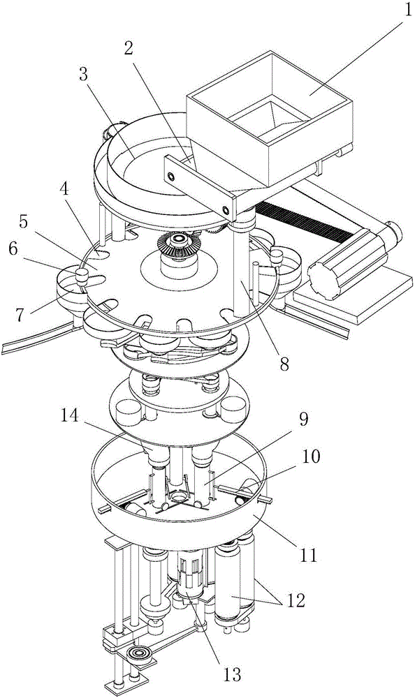
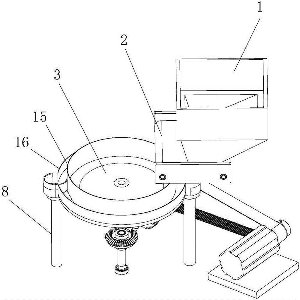
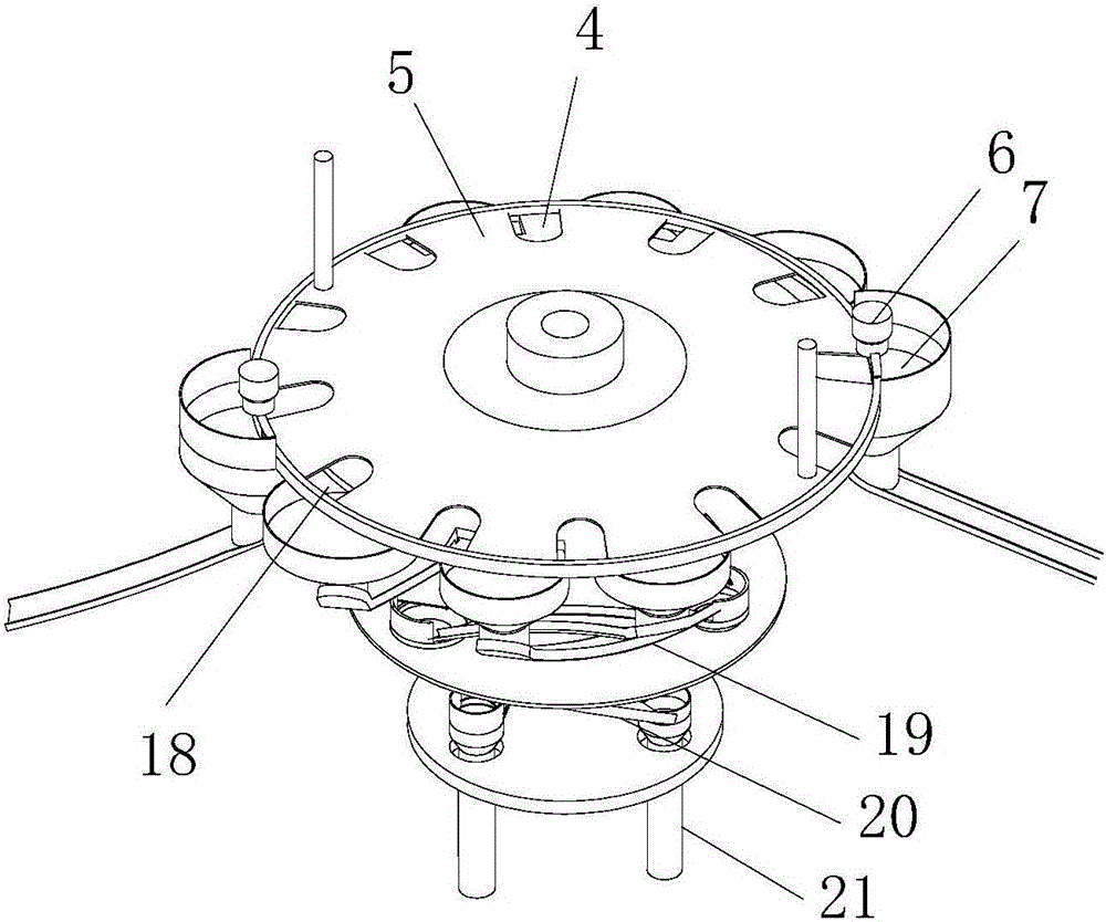
[0025] figure 1 It is a structural schematic diagram of the present invention; as shown in the figure, the coin sorting system of the present embodiment, the coin sorting system, includes a sorting module; the sorting module includes a coin-in device, a coin receiving cylinder 8 and a sorting tray; The sorting tray includes a tray 4 and a toothed chuck 5 coaxially rotatable, and the tray 4 is distributed with a plurality of sorting openings 18 which are successively increased in size along the circumferential direction, and the sorting opening 18 is used to make the Coins of a fixed size pass through to achieve sorting, and the tooth slots of the toothed chuck 5 can drive individual coins in the coin receiving cylinder 8 to pass through each sorting port 18 for sorting; a large number of mixed coins enter through the coin feeding device into the coin collection cylinder 8 and piled up into a stack of coins, the toothed chuck 5 in the sorting tray has a plurality of tooth groov...
PUM
 Abstract
Description
Claims
Application Information