Difference connector and shell component thereof

A differential connector and shell technology, which is applied to the parts of the connection device, the protective grounding/shielding device of the connection part, and the connection, etc., can solve the problems of destroying the integrity of the transmission line signal, affecting the quality of signal transmission, and electromagnetic leakage. Achieve convenient installation, reduce the number of installations, and eliminate electromagnetic interference

Active Publication Date: 2016-12-07
CHINA AVIATION OPTICAL-ELECTRICAL TECH CO LTD
View PDF14 Cites 12 Cited by
  • Summary
  • Abstract
  • Description
  • Claims
  • Application Information

AI Technical Summary

Problems solved by technology

[0002] In a traditional differential connector, the shell part of the connector is provided with an empty slot for installing a shielding plate. For example, the fully shielded differential connector disclosed by the Chinese patent with the announcement of CN104300313A and the publication date of 2015.01.21 includes a shell The differential module includes an insulator, a differential pair, and a grounding pin, that is, a grounding contact. The housing part is provided with an insertion hole corresponding to the differential pair and the grounding pin, and at least one side of the insulator is provided with a walking Wire shields, there are wiring shields between any differential modules, at least one side of the plug-in section of the differential pair is provided with end shields, there are end shields between the corresponding differential pairs of any two differential modules, and the end shields The shield is electrically connected to the corresponding wiring shield. During use, the end shield is blocked between the differential pairs of the two adjacent differential modules, thereby preventing the two differential pairs from being connected. Electromagnetic interference between them, and then solve the problem that the existing differential connector destroys the signal integrity of the transmission line, but when this differential connector is used, the differential pairs of adjacent differential modules still have electromagnetic leakage in multiple areas and are affected , ultimately affecting the quality of signal transmission

Method used


Image

  • Difference connector and shell component thereof
  • Difference connector and shell component thereof
  • Difference connector and shell component thereof

Examples


Embodiment Construction

[0026] Embodiments of the present invention will be further described below in conjunction with the accompanying drawings.

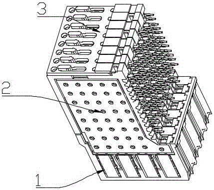
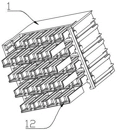
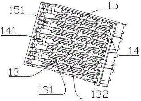
[0027] In the specific embodiment of the differential connector of the present invention, the end of the existing differential connector is only shielded by the shielding sheet, the shielding effect is not good, and it is limited by the volume of the housing part, the cylindrical fully shielded The end shielding sheet cannot be applied to the original differential module, and the use of the cylindrical end shielding sheet needs to change the structure of the differential module. The present invention is based on reducing the electromagnetic interference between the differential pairs corresponding to adjacent differential modules as much as possible For the purpose, the differential connector is designed as follows:

[0028] Such as Figure 1 to Figure 8 As shown, the differential connector includes a housing part 1, a differential module 2, and a fixin...


PUM


Abstract

The invention relates to the field of electric connectors, and especially relates to a difference connector and a shell component thereof. The difference connector comprises the shell component and more than two difference modules; each of the difference modules comprises an insulator, a differential pair and a grounding contact; the shell component comprises a shell, wherein the shell is provided with a plug hole which is corresponding to a plug end of the differential pair; the shell is provided with an end shielding part which is corresponding to the plug end of the differential pair; shielding slots extending along a plug direction of the plug end of the differential pair are arranged on the end shielding part; the openings of various shielding slots are towards the same direction; and the plug end of the differential pair is arranged in the shielding slots and isolated from a plug end of a differential pair which is adjacent to the same difference module. The difference connector and the shell component thereof provided by the invention solve the problem of electromagnetic interferences existing between differential pairs of the adjacent difference modules of the current difference connector.

Description

technical field [0001] The invention relates to the field of electrical connectors, in particular to differential connectors and housing parts thereof. Background technique [0002] In a traditional differential connector, the shell part of the connector is provided with an empty slot for installing a shielding plate. For example, the fully shielded differential connector disclosed by the Chinese patent with the announcement of CN104300313A and the publication date of 2015.01.21 includes a shell The differential module includes an insulator, a differential pair, and a grounding pin, that is, a grounding contact. The housing part is provided with an insertion hole corresponding to the differential pair and the grounding pin, and at least one side of the insulator is provided with a walking Wire shields, there are wiring shields between any differential modules, at least one side of the plug-in section of the differential pair is provided with end shields, there are end shield...

Claims


Application Information

Patent Timeline
Patent Type & Authority Applications(China)
IPC IPC(8): H01R13/648H01R13/6581
CPCH01R13/648H01R13/6581
Inventor 袁俊峰马陆飞周国奇
Owner CHINA AVIATION OPTICAL-ELECTRICAL TECH CO LTD
Why Eureka
Try Eureka