Nail head assembly for tst stapler for treating hemorrhoids

A stapler and component technology, applied in the direction of surgical fixation nails, etc., can solve the problems that the positioning accuracy cannot be further improved, affect the stability of the anvil seat assembly, and affect the formation of staples, etc., to achieve shortened operation time, large transmission force, and thrust uniform effect

Active Publication Date: 2018-07-20
常州创捷微创医疗器械有限公司
View PDF18 Cites 2 Cited by
  • Summary
  • Abstract
  • Description
  • Claims
  • Application Information

AI Technical Summary

Problems solved by technology

During the operation, it is necessary to put in the TST two-hole anoscope first, and then put in the circular hemorrhoid stapler. Therefore, the operation is complicated and the operation time is long, causing great pain to the patient.
Secondly, since the drive shaft of the circular hemorrhoid stapler is located in the center of the shell, the anvil assembly and the staple cartridge assembly are connected and positioned through the drive shaft. Due to the single-axis positioning, there are certain manufacturing and assembly errors in the stapling instrument, which makes the The positioning accuracy between the nail anvil assembly and the staple cartridge assembly cannot be further improved, so when operating the moving force of the nail anvil assembly, it will affect the stability of the anvil assembly when moving, and ultimately affect the forming of staples
Furthermore, during the forming process of staples, the thrust acts on the anvil seat assembly through the drive shaft, and the single-axis transmission results in a small transmission force.

Method used


Image

  • Nail head assembly for tst stapler for treating hemorrhoids
  • Nail head assembly for tst stapler for treating hemorrhoids
  • Nail head assembly for tst stapler for treating hemorrhoids

Examples


Embodiment Construction

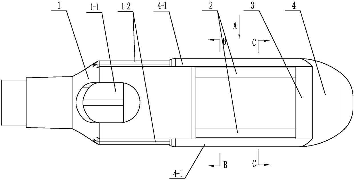
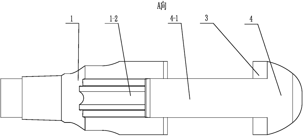
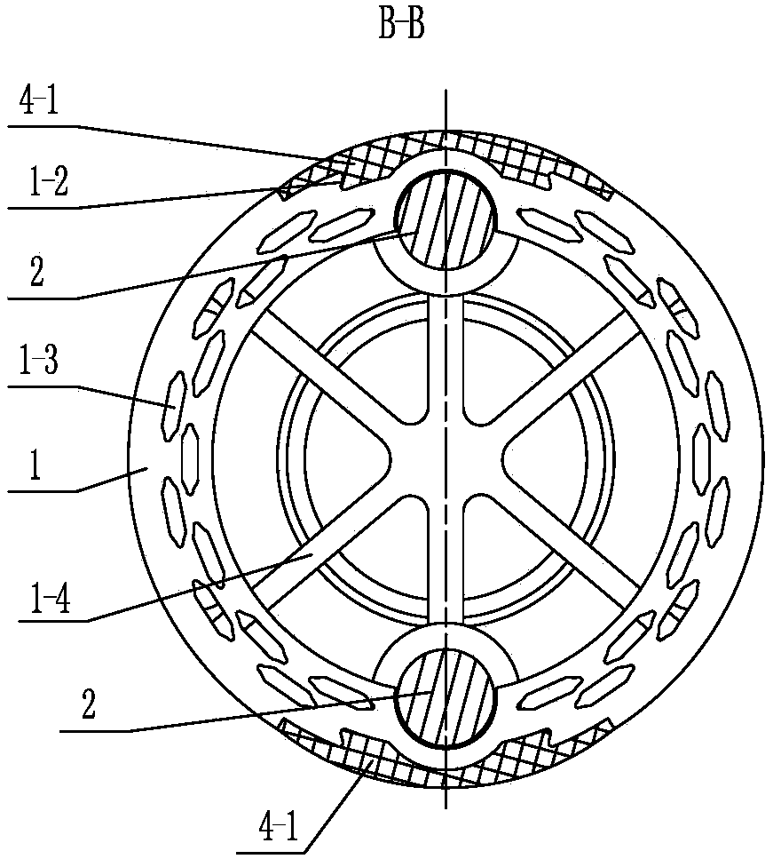
[0018] See Figure 1-7 As shown, the nail head assembly of the TST stapler for treating hemorrhoids of the present invention includes an abutment seat assembly and a nail cartridge assembly 1 with nail holes 1-3 at the front end. See Figure 1-7 As shown, the nail anvil assembly of the present invention includes a shield 4 with a spherical surface at the front and an anvil 3, and the shield 4 includes a connecting seat 4-3 at the front and at least two shields 4 extending backward for blocking tissue -1, it is convenient to introduce into the anus through the spherical surface, and the nail anvil 3 with the nail groove 3-1 is installed on the connecting seat 4-3. See Figure 5 As shown, the connecting seat 4-3 at the front portion of the shield 4 of the present invention is provided with a threaded hole, and the nail anvil 3 is provided with a corresponding nail hole, and the fastener 5 can be passed through the nail hole on the nail anvil 3 to Screwed on the connecting sea...


PUM


Abstract

The invention relates to a nail head assembly used for a haemorrhoids treatment TST stapler. A nail-pushing base assembly comprises a protective cover of which the front part has a spherical face as well as a nail anvil; wherein the protective cover comprises a connection base on the front part as well as at least two protective plates which extend backwards and are used to block a tissue; the nail anvil with a nail groove is installed on the connection base; a hole part of the nail anvil communicates with the part outside the protective cover spherical face via a through hole in the connection base; two positioning pull rods which are installed on the nail anvil or / and the protective cover and can be moved simultaneously are located at inner sides of the corresponding protective plates and extend out from the protective plates; each positioning pull rod passes through an upper positioning hole in a nail cabin assembly and can be moved; at least two guide parts matched with the protective plates are disposed on peripheries of the nail cabin assembly; the protective plates can be moved axially along the guide parts and cannot be rotated; and at least two operation holes used for observation and line pulling are formed in the nail cabin assembly. The nail head assembly provided by the invention has the advantages that the structure is rational; positioning accuracy and stability of the nail-pushing base assembly and the nail cabin assembly can be increased; push force can be increased; and surgical operations are convenient.

Description

technical field [0001] The invention relates to a nail head assembly of a TST stapler for treating hemorrhoids, and belongs to the technical field of hemorrhoid staplers. Background technique [0002] The PPH operation method is stapler hemorrhoidectomy, which is suitable for all kinds of hemorrhoids, especially for patients with severe internal hemorrhoids and partial rectal mucosal prolapse. The mechanism is to circularly resect the mucosa and submucosal tissue of the lower end of the rectum near the upper edge of the prolapsed internal hemorrhoid, and anastomose the distal and proximal mucosa at the same time, so that the prolapsed internal hemorrhoid and mucosa are suspended upwards. Hang and pull, no more prolapse. At the same time, because the artery supplying hemorrhoids from the superior rectal artery located in the submucosa is cut off, the blood supply of hemorrhoids is reduced after operation. Therefore, the exact name of the operation should be "circumcision of...

Claims


Application Information

Patent Timeline
Patent Type & Authority Patents(China)
IPC IPC(8): A61B17/115
CPCA61B17/1155
Inventor 陈激陈贵
Owner 常州创捷微创医疗器械有限公司
Why Eureka
Try Eureka