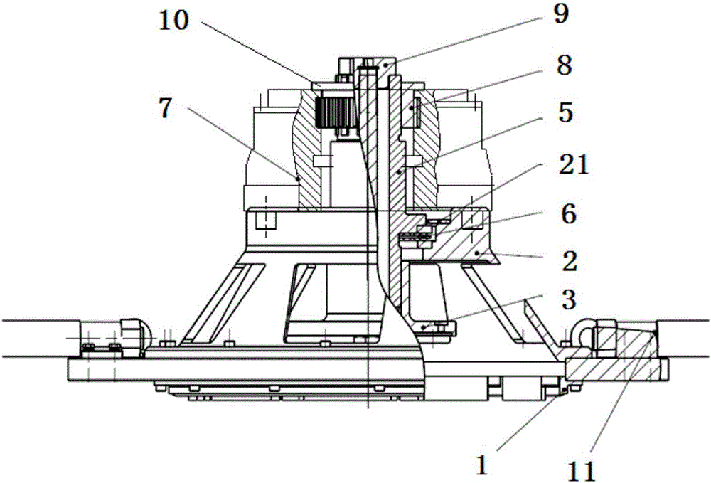
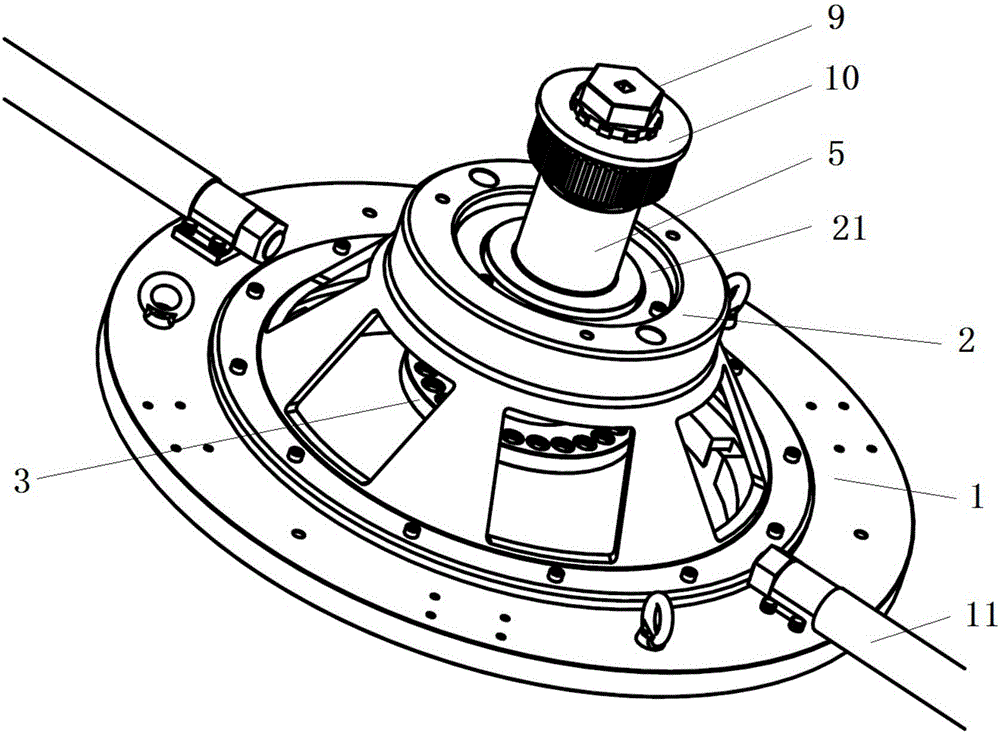
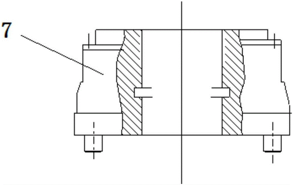
Disassembling and assembling device for high-pressure turbine front baffle

A high-pressure turbine and front baffle technology, applied in hand-held tools, manufacturing tools, etc., can solve the problems of baffle damage, low work efficiency, and inability to obtain baffle assembly and decomposition torque, so as to avoid damage and eliminate discomfort. Effect

Active Publication Date: 2016-12-14
AECC SHENYANG ENGINE RES INST
View PDF10 Cites 10 Cited by
  • Summary
  • Abstract
  • Description
  • Claims
  • Application Information

AI Technical Summary

Problems solved by technology

[0002] At present, some aero-engine high-pressure turbine front baffles adopt a boltless structure. However, there has been a lack of effective methods and devices for the assembly and disassembly of the baffle, and the assembly and disassembly of the structure can only be realized by relying on impact loads.
At the current level of technology, the assembly and disassembly torque of the baffle cannot be obtained. At the same time, the assembly and disassembly of the baffle requires at least three operators to cooperate and apply impact loads many times to complete. The work efficiency is relatively low, and there are certain safety hazards
In addition, the impact load of assembly decomposition will cause certain damage to the baffle, and the reaction force of the impact load will also cause certain discomfort to the operator

Method used


Image

  • Disassembling and assembling device for high-pressure turbine front baffle
  • Disassembling and assembling device for high-pressure turbine front baffle
  • Disassembling and assembling device for high-pressure turbine front baffle

Examples


Embodiment Construction

[0029] In order to make the objectives, technical solutions and advantages of the present invention clearer, the technical solutions in the embodiments of the present invention will be described in more detail below in conjunction with the drawings in the embodiments of the present invention. In the drawings, the same or similar reference numerals denote the same or similar elements or elements having the same or similar functions throughout. The described embodiments are some, but not all, embodiments of the invention. The embodiments described below by referring to the figures are exemplary and are intended to explain the present invention and should not be construed as limiting the present invention. Based on the embodiments of the present invention, all other embodiments obtained by persons of ordinary skill in the art without creative efforts fall within the protection scope of the present invention. Embodiments of the present invention will be described in detail below ...


PUM


Abstract

The invention relates to design of auxiliary equipment for high-pressure turbines of aircraft engines, in particular to a disassembling and assembling device for a high-pressure turbine front baffle. The disassembling and assembling device comprises an assembling and disassembling ring, a supporting frame, a connecting seat, an axial load pull rod, a spline shaft, a torque amplifier, a spline transition section and an axial load nut, wherein the assembling and disassembling ring is arranged on one side of the front baffle in a sleeving mode; the supporting frame is coaxially fixed to one side of the assembling and disassembling ring; the connecting seat is located in an inner cavity of the supporting frame and fixedly connected with a high-pressure turbine disc through a fixing part of the connecting seat; one end of the axial load pull rod coaxially penetrates through a through hole of the fixing part; the axial load pull rod is coaxially sleeved with the spline shaft, the outer ring face of the spline shaft is arranged at one end of the supporting frame through a thrust ball bearing, and one end of the spline shaft is arranged in an accommodating part of the connecting seat in a matched mode through splines; the torque amplifier is coaxially and fixedly arranged at the end, away from the assembling and disassembling ring, of the supporting frame; the spline transition section is arranged between the spline shaft and the torque amplifier; and the axial load nut is arranged at one end of the axial load pull rod. By means of the disassembling and assembling device for the high-pressure turbine front baffle, torque required for assembling and disassembling of the front baffle can be stably loaded.

Description

technical field [0001] The invention relates to the design of auxiliary equipment for high-pressure turbines of aero-engines, in particular to a disassembly and assembly device for front baffles of high-pressure turbines. Background technique [0002] At present, some aero-engine high-pressure turbine front baffles adopt a boltless structure. However, there has been a lack of effective methods and devices for the assembly and disassembly of the baffle, and the assembly and disassembly of the structure can only be realized by relying on impact loads. At the current level of technology, the assembly and disassembly torque of the baffle cannot be obtained. At the same time, the assembly and disassembly of the baffle requires at least three operators to apply impact loads for multiple times. The work efficiency is relatively low, and there are certain safety hazards. In addition, the impact load of assembly decomposition will cause certain damage to the baffle, and the reaction ...

Claims


Application Information

Patent Timeline
IPC IPC(8): B25B27/00
CPCB25B27/00
Inventor 杨法立卢文彪孙贵青叶茂丰少宝曹艳魏秀鹏常维东王洪伟
Owner AECC SHENYANG ENGINE RES INST
Why Eureka
Try Eureka