AI technical title is built by Patsnap AI team. It summarizes the technical point description of the patent document.
A safety protection and elevator car technology, applied in the field of elevators, can solve problems such as elevator car shaking or vibration, passengers falling and being injured
Inactive Publication Date: 2016-12-14
CHONGQING WESTER ELEVATOR
View PDF0 Cites 1 Cited by
Summary
Abstract
Description
Claims
Application Information
AI Technical Summary
This helps you quickly interpret patents by identifying the three key elements:
Problems solved by technology
Method used
Benefits of technology
Problems solved by technology
When the elevator fails, the elevator car may shake or vibrate, causing passengers to fall and be injured
Method used
Image
Click on the blue label to locate the original text in one second.
Reading with bidirectional positioning of images and text.
Examples
Embodiment 1
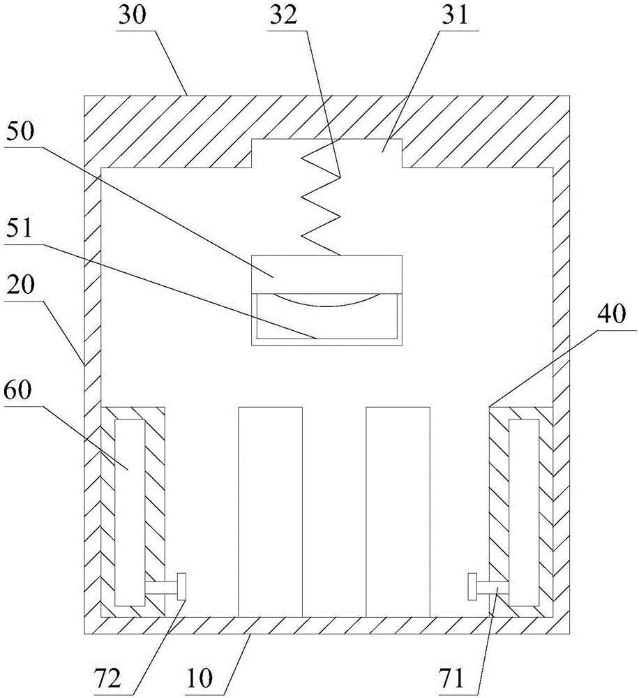
[0026] Such as figure 1 As shown, a safety protection structure for an elevator car includes a car body, a protective column 40, a lighting lamp 50, an air bag 60, a pressure relief pipe 71 and a pressure relief valve 72;
[0027] Described car body comprises base plate 10, side plate 20, top plate 30; Described base plate 10 is fixed on the bottom of described side plate 20, and described top plate 30 is fixed on the top of described side plate 20, and described base plate 10, The side board 20 and the top board 30 together define the seating space of the elevator car;
[0028] The elastic protection column 40 is fixed on the bottom plate 10, the elastic protection column 40 is attached to the side plate 20, and a plurality of the elastic protection columns 40 are arranged at equal intervals;
[0029] The airbag 60 is arranged inside the elastic protective pillar 40, the pressure relief pipe 71 passes through the elastic protective pillar 60 and communicates with the airbag ...
Embodiment 2
[0033] Such as figure 1 As shown, in this embodiment, on the basis of Embodiment 1, a fixing groove 31 is provided on the top plate 30, and a spring 32 is arranged in the fixing groove 31; one end of the spring 32 and the bottom of the fixing groove 31 The other end of the spring 32 is connected to the lighting lamp 50; the lighting lamp 50 is located in the fixing groove 31 under the action of the elastic force of the spring 32.
[0034] Usually, the lighting conditions in the elevator are limited, and the lights in the elevator are all arranged on the top of the car, so that when passengers look down, most of the lights will be blocked by their heads, affecting their sight. After the passenger was injured and fell to the ground, due to poor vision, other passengers were affected to rescue the injured passenger. For this reason, in the present invention, the illuminating lamp 50 is fixed on the top plate 30 through the spring 32 . When it is necessary to rescue an injured p...
Embodiment 3
[0036] Such as figure 1 As shown, this embodiment is based on Embodiment 2, and the bottom of the illuminating lamp 50 is provided with a handle 51 .
[0037] A handle 51 is provided to facilitate pulling down the illuminating lamp 50 .
PUM
Abstract
The invention discloses a safety protection structure for a lift car. The safety protection structure comprises a car body, protection columns, a lighting lamp, air bags, pressure relief pipes and pressure relief valves, wherein the car body comprises a bottom plate, side plates and a top plate; the bottom plate is fixed at the bottom ends of the side plates; the top plate is fixed at the top ends of the side plates; the bottom plate, the side plates and the top plate jointly define a standing space of the lift car; elastic protection columns are fixed on the bottom plate and lean against the side plates; the multiple elastic protection columns are arranged in a uniformly spaced manner; the air bags are arranged in the elastic protection columns; the pressure relief pipes penetrate through the elastic protection columns and communicate with the air bags; the pressure relief valves are arranged on the pressure relief pipes; and the lighting lamp is fixed on the top plate. The safety protection structure can effectively protect the head of a passenger.
Description
technical field [0001] The invention relates to elevator technology, in particular to an elevator car safety protection structure. Background technique [0002] Elevator is a kind of vertical elevator powered by electric motor, equipped with a car, used for transportation of people in multi-storey buildings. Since the elevator car runs in the shaft provided in the building, passengers are in a relatively closed space when taking the elevator. When the elevator fails, the elevator car may shake or vibrate, causing passengers to fall and be injured. Since the passengers are in a closed space, once the elevator stops working, it is difficult for the injured passengers to be treated in time. Therefore, improving the safety of the elevator car is a top priority. Contents of the invention [0003] The purpose of the present invention is to overcome the above-mentioned problems of the prior art and provide a high-safety elevator car safety protection structure [0004] The pur...
Claims
Application Information
Patent Timeline
Application Date:The date an application was filed.
Publication Date:The date a patent or application was officially published.
First Publication Date:The earliest publication date of a patent with the same application number.
Issue Date:Publication date of the patent grant document.
PCT Entry Date:The Entry date of PCT National Phase.
Estimated Expiry Date:The statutory expiry date of a patent right according to the Patent Law, and it is the longest term of protection that the patent right can achieve without the termination of the patent right due to other reasons(Term extension factor has been taken into account ).
Invalid Date:Actual expiry date is based on effective date or publication date of legal transaction data of invalid patent.

