Intelligent safe box transmission mechanism
A technology of transmission mechanism and safe, applied in the field of intelligent safe, can solve the problems of instability, high cost, unreasonable transmission mechanism design, etc., and achieve the effect of convenient installation and stable control.
- Summary
- Abstract
- Description
- Claims
- Application Information
AI Technical Summary
Problems solved by technology
Method used
Image

Examples
Embodiment 1
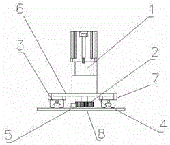
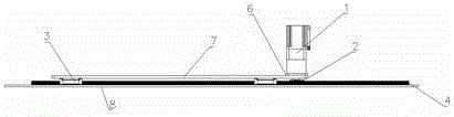
[0017] refer to Figure 1-2 , an intelligent safe transmission mechanism, comprising a bottom plate 8, the upper end of the bottom plate 8 is provided with a first fixing groove and two second fixing grooves, the first fixing groove is located between the two second fixing grooves, and the first fixing groove is fixed There is a rack 5, and the wire rail 4 is fixed in the two second fixing grooves, the rack 5 and the wire rail 4 are arranged in parallel, the rack 5 is installed in the first fixing groove, and the wire rail 4 is installed in the second fixing groove , the installation is more convenient, two sliders 3 are installed on each line rail 4, the upper ends of the two sliders 3 on the same line rail 4 are provided with a mounting plate 7, and the upper ends of the two mounting plates 7 are connected by a fixed plate 6 , and the fixed plate 6 is fixed on one side edge of the mounting plate 7, the upper end of the fixed plate 6 is fixed with the drive device 1, the lowe...
Embodiment 2
[0021] refer to Figure 1-2 , an intelligent safe transmission mechanism, comprising a bottom plate 8, the upper end of the bottom plate 8 is provided with a rack 5 and two wire rails 4, the rack 5 is located between the two wire rails 4, the rack 5 and the wire rails 4 are arranged in parallel, Two sliders 3 are installed on each line rail 4, and the upper ends of the two sliders 3 on the same line rail 4 are provided with a mounting plate 7, and the upper ends of the two mounting plates 7 are connected by a fixed plate 6, and the fixed plate 6 Fixed on one side edge of the mounting plate 7, the upper end of the fixing plate 6 is fixed with a driving device 1, the lower end of the driving device 1 is connected with a drive shaft, the driving shaft runs through the fixing plate 6 and extends to the bottom of the fixing plate 6, the drive shaft 6 The gear 2 meshing with the rack 5 is installed at the lower end, through the meshing of the rack 5 and the gear 2, the mounting plat...
PUM
 Abstract
Description
Claims
Application Information
 - R&D
- Intellectual Property
- Life Sciences
- Materials
- Tech Scout
- Unparalleled Data Quality
- Higher Quality Content
- 60% Fewer Hallucinations
Browse by: Latest US Patents, China's latest patents, Technical Efficacy Thesaurus, Application Domain, Technology Topic, Popular Technical Reports.
© 2025 PatSnap. All rights reserved.Legal|Privacy policy|Modern Slavery Act Transparency Statement|Sitemap|About US| Contact US: help@patsnap.com