
Air intake heating system of engine and power control method thereof

A heating power and heating system technology, applied in the direction of engine components, machines/engines, charging systems, etc., can solve the problems of non-adjustable intake heater power and poor relay versatility

Active Publication Date: 2018-12-14
WEICHAI POWER CO LTD
View PDF2 Cites 2 Cited by
  • Summary
  • Abstract
  • Description
  • Claims
  • Application Information

AI Technical Summary

Problems solved by technology

[0004] In the above air intake heater, the continuous working time of the air intake heater is controlled by a relay, the power of the intake air heater cannot be adjusted, and different models require relays with different powers to meet the specific displacement requirements. Therefore, the relay’s poor versatility

Method used


Image

  • Air intake heating system of engine and power control method thereof
  • Air intake heating system of engine and power control method thereof
  • Air intake heating system of engine and power control method thereof

Examples


Embodiment Construction

[0056] In order to enable those skilled in the art to better understand the technical solutions of the present invention, the present invention will be further described in detail below in conjunction with the accompanying drawings and specific embodiments.

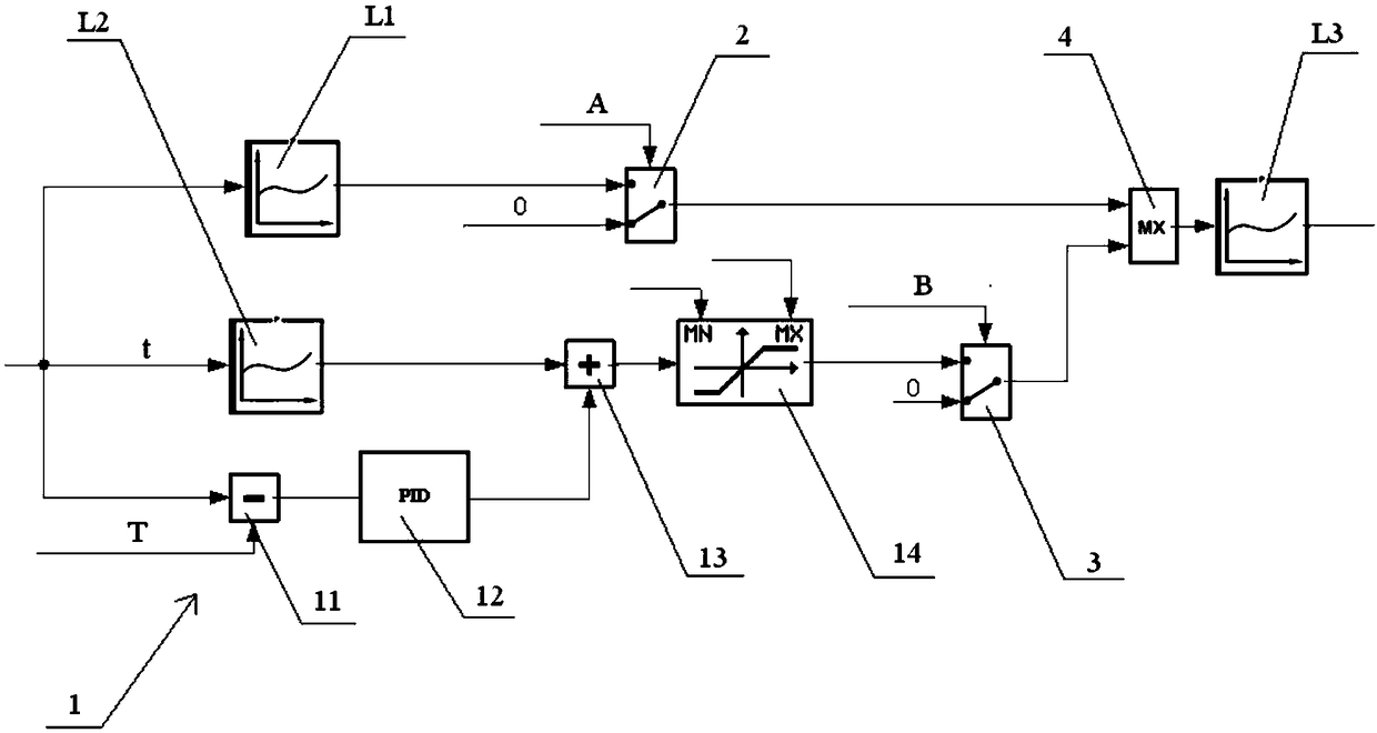
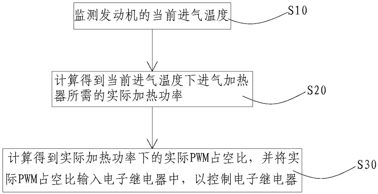
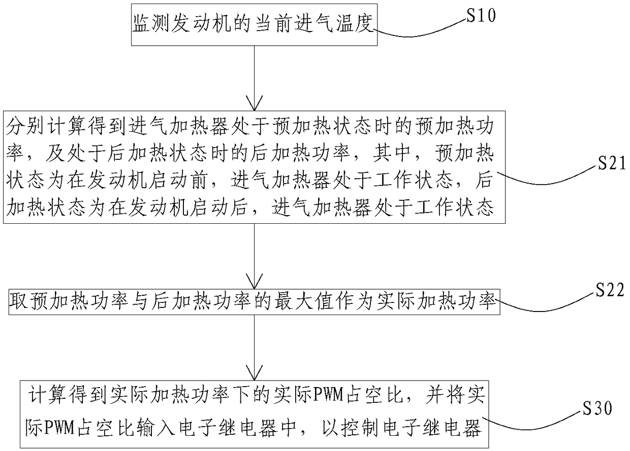
[0057] Please refer to the attached Figure 1-6 ,in, figure 1 It is a logical schematic diagram of the control device of the air intake heating system of the engine provided by the present invention; figure 2 The flow chart of the control method of the air intake heating system of the engine provided by the present invention in the first specific embodiment; image 3 The flow chart of the control method of the air intake heating system of the engine provided in the present invention in the second specific embodiment; Figure 4 for image 3 The flowchart of step S21 in; Figure 5 for Figure 4 The flowchart of step S216 in; Image 6 for Figure 4 The flow chart of step S214.

[0058] In a specific embodiment, the ...


PUM


Abstract

The invention discloses a power control method of an air inlet heating system of an engine. The air inlet heating system comprises an air inlet heater, the air inlet heater is controlled by an electronic relay, and the power control method is used for controlling the electronic relay and comprises following steps: (10), the current air inlet temperature of the engine is monitored; (20), the actual heating power needed by the air inlet heater at the current air inlet temperature is obtained through calculation; (30), the actual PWM duty ratio under the actual heating power is obtained through calculation, and is input into the electronic relay to control the electronic relay, and therefore the power of the air inlet heater can be continuously adjusted, the electronic relay can adapt to power requirements of different air inlet heaters, and generality of the method is improved. The invention further discloses the air inlet heating system of the engine.

Description

technical field [0001] The invention relates to the technical field of engines, in particular to an engine intake heating system and a power control method thereof. Background technique [0002] When the engine is in a low temperature state, due to the low temperature of the air entering the engine cylinder, the fuel injected by the engine into the cylinder cannot reach its ignition point when the piston compression ends, resulting in the failure of the engine to start normally. In response to this situation, an air intake heater for engine heating was developed. Normally, the air intake heater is installed at the air intake of the engine to heat the intake air of the engine, so as to ensure that the engine can still start normally at low temperature and improve the performance of the engine. [0003] The air intake heater is controlled by a relay, and the commonly used air intake heater relay is usually a mechanical relay. When it is working, because it is often impacted b...

Claims


Application Information

Patent Timeline
Patent Type & Authority Patents(China)
IPC IPC(8): F02M31/13
CPCF02M31/13
Inventor 王贵琛徐增密李文广
Owner WEICHAI POWER CO LTD
Learn More