High-frequency high-power multi-waveform power supply for differential arc oxidization
A micro-arc oxidation, high-power technology, applied in output power conversion devices, DC power input into DC power output, electrical components and other directions, can solve the problem of large volume, high energy consumption, and the output waveform cannot be continuously adjusted in a wide range, etc. question
- Summary
- Abstract
- Description
- Claims
- Application Information
AI Technical Summary
Problems solved by technology
Method used
Image
Examples
specific Embodiment approach 1
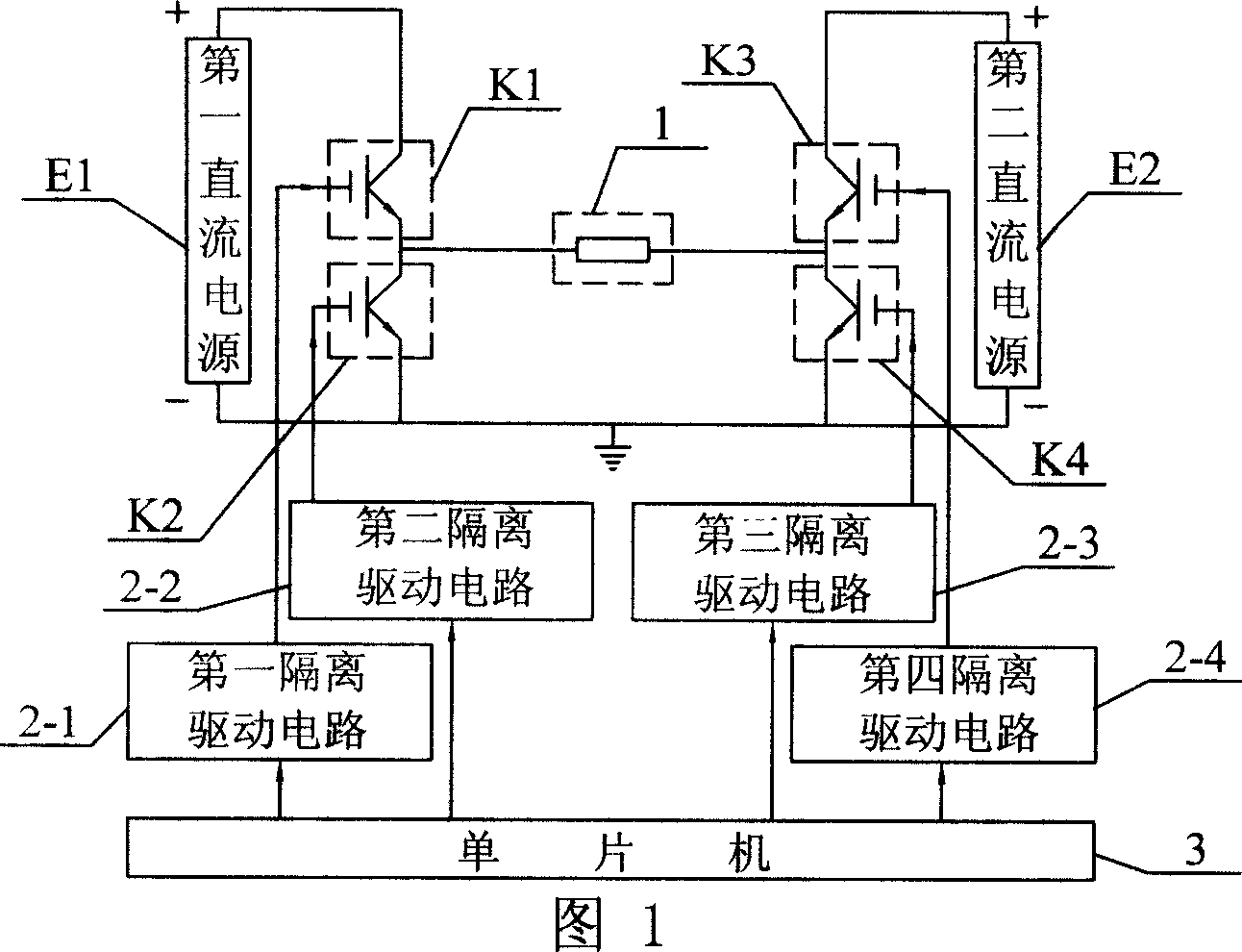
[0005] Specific Embodiment 1: The present embodiment will be specifically described below with reference to FIG. 1 . It consists of the same two DC power supplies, the same four power switches, the same four isolated drive circuits and the single chip microcomputer 3, the first power switch K1 to the fourth power switch K4 are all insulated gate bipolar transistors, the first direct current The positive pole of the current power supply E1 is connected to the collector of the first power switch K1, the emitter of the first power switch K1 is connected to one end of the micro-arc oxidation working tank 1 and the collector of the second power switch K2, and the other end of the micro-arc oxidation working tank 1 One end is connected to the emitter of the third power switch K3 and the collector of the fourth power switch K4, the collector of the third power switch K3 is connected to the positive pole of the second DC power supply E2, and the negative pole of the second DC power sup...
specific Embodiment approach 2
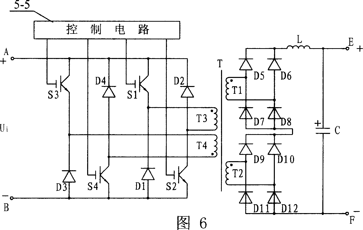
[0006] Specific Embodiment 2: The present embodiment will be specifically described below with reference to FIG. 5 and FIG. 6 . The difference between this embodiment and Embodiment 1 is that the first DC power supply E1 and the second DC power supply E2 are respectively composed of an EMI and rectification circuit 5-1, a power factor correction circuit 5-2, a switch adjustment circuit 5-3, and a rectification circuit 5-1. The filter circuit 5-4 and the control circuit 5-5 are composed, the input end of the EMI and rectification circuit 5-1 is connected to the AC power supply, the output end of the EMI and rectification circuit 5-1 is connected with the input end of the power factor correction circuit 5-2, The output end of the power factor correction circuit 5-2 is connected to one input end of the switch adjustment circuit 5-3, the other input end of the switch adjustment circuit 5-3 is connected to the output end of the control circuit 5-5, and the switch adjustment circuit ...
specific Embodiment approach 3
[0007]Specific Embodiment Three: The present embodiment will be specifically described below in conjunction with FIG. 7 . The difference between this embodiment and the second embodiment is that the control circuit 5-5 is implemented by PWM control and frequency adjustment circuit 5-5-1, the same two minimum and maximum pulse width limiting circuits 5-5-2 and the same Composed of two isolated drive circuits 5-5-3, the PWM control and frequency adjustment realization circuit 5-5-1 consists of three integrated operational amplifiers, a PWM integrated control chip U1 of model UC3825, nine resistors, two potentiometers, Composed of three capacitors, transistor Q1 and No. 51 diode D51, one end of No. 6 resistor R6 is connected to the output end of rectifier filter circuit 5-4, the other end of No. One end of R7 is connected to the inverting input end of No. 1 integrated operational amplifier A1, the other end of No. 7 resistor R7 is connected to one end of No. 3 capacitor C3, the o...
PUM
 Abstract
Description
Claims
Application Information
 - R&D
- Intellectual Property
- Life Sciences
- Materials
- Tech Scout
- Unparalleled Data Quality
- Higher Quality Content
- 60% Fewer Hallucinations
Browse by: Latest US Patents, China's latest patents, Technical Efficacy Thesaurus, Application Domain, Technology Topic, Popular Technical Reports.
© 2025 PatSnap. All rights reserved.Legal|Privacy policy|Modern Slavery Act Transparency Statement|Sitemap|About US| Contact US: help@patsnap.com


