Three-ring reducer dedicated to steel billet roll table

A three-ring deceleration, roller table technology, applied in mechanical equipment, transmission parts, gear transmission and other directions, can solve the problems of large volume, difficult motor installation, large-area parking, etc.

Inactive Publication Date: 2016-12-14
JIANGSU TAILONG MACHINERY GRP CO CO LTD
View PDF6 Cites 3 Cited by
  • Summary
  • Abstract
  • Description
  • Claims
  • Application Information

AI Technical Summary

Problems solved by technology

However, the current reducer has good impact resistance and overload performance, but the volume is too large, and the installation of the reducer including the motor is very difficult; the reducer with a smaller size, such as a modular geared motor, cannot withstand the impact load, and the overload performance is not good. It is easy to cause large-scale parking and seriously affect the production and transportation of steel billets

Method used


Image

  • Three-ring reducer dedicated to steel billet roll table
  • Three-ring reducer dedicated to steel billet roll table

Examples


Embodiment Construction

[0012] Below in conjunction with accompanying drawing, the specific implementation manner of technical scheme is described in further detail:

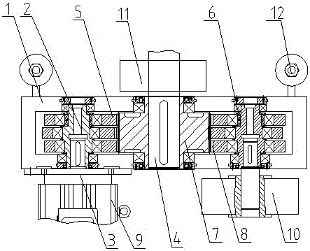
[0013] The special three-ring reducer for the billet roller table includes a box body 1. Three parallel shafts located on the same horizontal plane are installed in the box body 1. The two ends of each shaft are supported on the box body 1 by bearings. The shafts on both sides are eccentric crankshafts. The middle part of the rotating shaft on both sides is a three-section crankshaft 3 with a difference of 120 degrees between adjacent sections. Two sections of the three-section crankshaft 3 have the same diameter, and the diameter of the other section of the crankshaft is smaller than the other two sections. A compensation shaft is sleeved on the crankshaft section with a small diameter. Sleeve 6; the left shaft is the input shaft 3, one end of the input shaft 3 protrudes from the outside of the box body 1 and is connected to the input ...


PUM


Abstract

The invention relates to a three-ring reducer dedicated to a steel billet roll table. The three-ring reducer comprises a box body, wherein three parallel rotating shafts positioned in the same horizontal plane are mounted inside the box body; the two ends of the rotating shafts are supported on the box body through bearings; the same and different ends of the middle rotating shaft and the rotating shafts on the two sides stretch out of the outer side of the box body; three three-ring plates sleeve the three rotating shafts; the rotating shafts on the two sides are connected with annular holes in the two sides of the three-ring plates through the bearings; an external gear is mounted on the middle rotating shaft; the external gear is matched with inner gear rings at the centers of the three-ring plates; the rotating shafts on the two sides are eccentric crank shafts; the middle parts of the rotating shafts on the two sides are three sections of crank shafts of which the adjacent sections have 120-degree difference; the annular holes in the two sides of the three three-ring plates respectively correspond to the three sections of crank shafts; the rotating shafts on the two sides are connected with input motors, or one of the rotating shafts on the two sides is connected with an input motor, and the other of the rotating shafts on the two sides is connected with a brake or an encoder; a table roll is arranged at the stretching end of the middle shaft; and the two sides of the table roll are connected with elastic damping pull rod devices.

Description

technical field [0001] The invention relates to a speed reducer, in particular to a special three-ring speed reducer for billet roller tables. Background technique [0002] The billet roller table is the basic equipment of the steel plant, which is used to convey the formed billets, profiles and other items. Due to the large volume and heavy weight of this type of steel, there is no other equipment on the production line that can replace the roller table to transport this type of steel, so the reliability of the roller table is very high, and the billet will have a strong impact on the roller table when the roller table is running. The impact force, and part of the impact force will be transmitted to the reducer of the drive part, so the reducer needs to have sufficient impact resistance and overload resistance. Since the distance between the rollers on the roller table is limited and there are many parts on the roller table, the requirements for the size of the reducer are...

Claims


Application Information

Patent Timeline
Patent Type & Authority Applications(China)
IPC IPC(8): F16H1/22F16H57/028
CPCF16H1/22F16H57/028
Inventor 朱明生殷爱国孔霞黄胜栋刘媛张介禄
Owner JIANGSU TAILONG MACHINERY GRP CO CO LTD
Why Eureka
Try Eureka