
Illumination device for projecting light in a predetermined illumination pattern on a surface

A technology for lighting devices and lighting patterns, applied in the field of lighting systems, to achieve the effect of reducing costs

Pending Publication Date: 2016-12-14
AGM AUTOMOTIVE
View PDF6 Cites 6 Cited by
  • Summary
  • Abstract
  • Description
  • Claims
  • Application Information

AI Technical Summary

Problems solved by technology

[0004] The present invention overcomes the disadvantages of prior art lighting devices for projecting predetermined lighting patterns on surfaces

Method used


Image

  • Illumination device for projecting light in a predetermined illumination pattern on a surface
  • Illumination device for projecting light in a predetermined illumination pattern on a surface
  • Illumination device for projecting light in a predetermined illumination pattern on a surface

Examples


Embodiment Construction

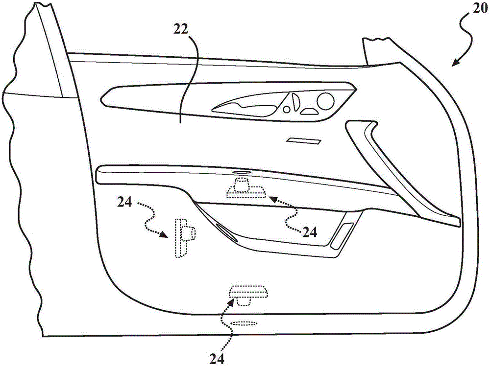
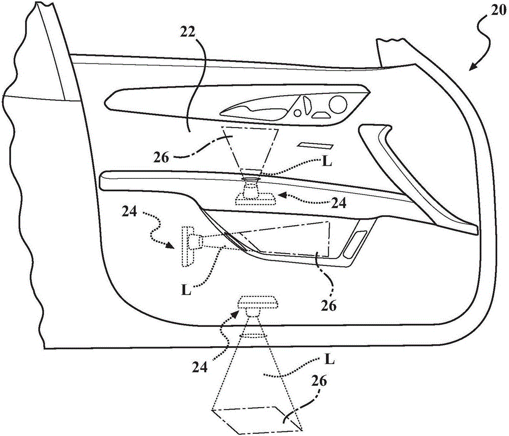
[0018] Referring now to the drawings, in which like reference numerals are used to indicate like structures, the lighting system is shown in figure 1 Expressed in 20. Lighting system 20 may be adapted for use in a vehicle for transporting one or more passengers. However, it should be appreciated that the lighting system 20 may be adapted for any system requiring lighting. The lighting system 20 is included in the figure 1 The surface shown in 22. The surface 22 may be defined by components within the vehicle interior including, but not limited to, door panels, vehicle flooring (such as carpet or floor mats in the passenger compartment or cargo area), and the vehicle roof. Furthermore, surface 3 may be defined by any suitable component of the exterior of the vehicle, including but not limited to body panels, vehicle glass and wheels. It should be appreciated that surface 22 may be defined by anything proximate to the vehicle, such as the ground on which the vehicle rests. ...


PUM


Abstract

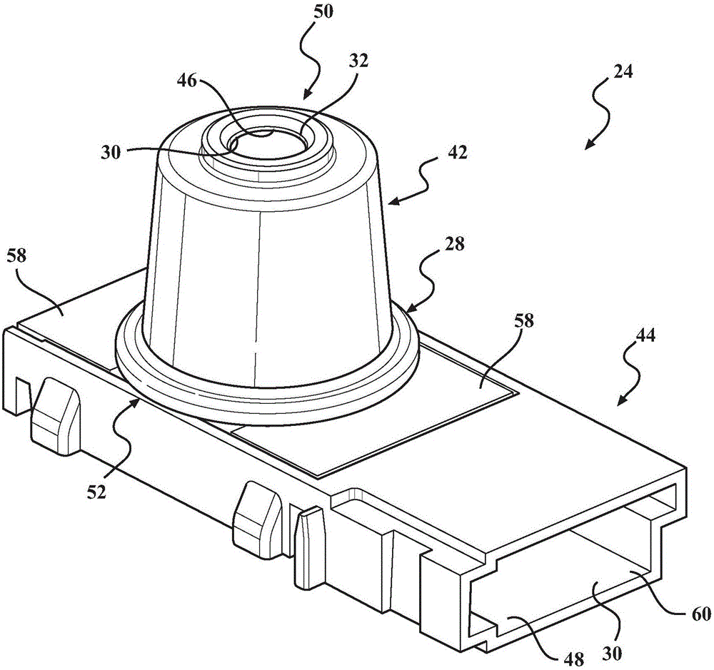
An illumination device projects light in a predetermined illumination pattern on a surface. The illumination device includes a housing having a cavity and an aperture. The illumination device includes a light module for selectively emitting the light and a screen at least partially disposed in the cavity between the light module and the aperture. The screen has at least one opening defining a base pattern configuration corresponding to the predetermined illumination pattern for aligning the light through the opening into the base pattern configuration and subsequently projecting the light through the aperture onto the surface in the predetermined illumination pattern. The illumination device includes a condensing lens disposed between the light module and the screen for collimating the light toward the screen and an objective lens arrangement disposed between the screen and the aperture for transforming the light from the base pattern configuration into the predetermined illumination pattern.

Description

technical field [0001] The present invention relates generally to a lighting system, and more particularly to a lighting device for projecting light in a predetermined lighting pattern on a surface. Background technique [0002] It is desirable in the automotive industry to provide a lighting device to illuminate surfaces inside a vehicle. In particular, it is desirable to illuminate the surface in a particular pattern or design. Illuminating interior surfaces with a particular pattern or design improves visibility in the interior near the illuminated surface in low light situations and is believed to be aesthetically appealing to viewers of the illuminated surface. One solution in this industry concerns a lighting system comprising a panel with the surface and a partly transparent part, the partially transparent part of which the panel has a certain pattern or design. A number of lighting devices such as light emitting diodes or optical fibers are placed behind the panel ...

Claims


Application Information

Patent Timeline
IPC IPC(8): F21S8/10F21V11/00F21V5/04F21V13/02F21V17/10F21V19/00F21V15/01F21W101/02F21W101/08F21Y115/30F21Y115/10F21W106/00F21W107/10
CPCF21S43/00F21V5/04F21V11/00F21V13/02F21V15/01F21V17/10F21V19/0025F21W2106/00F21W2107/10B60Q1/323B60Q2400/50B60Q3/60F21Y2115/30F21Y2115/10B60Q3/217
Inventor 威廉姆·亨利·迈克利兰史蒂文·斯科特·菲莱卡
Owner AGM AUTOMOTIVE
Learn More