A charging method and mobile terminal

A mobile terminal and charging method technology, applied in the direction of electric vehicles, current collectors, electrical components, etc., can solve the problems of slow response and poor flexibility of temperature detection methods, and achieve high flexibility, slow solution response, and high acquisition accuracy Effect

Active Publication Date: 2019-03-01
VIVO MOBILE COMM CO LTD
View PDF6 Cites 0 Cited by
  • Summary
  • Abstract
  • Description
  • Claims
  • Application Information

AI Technical Summary

Problems solved by technology

[0007] The invention provides a charging method and a mobile terminal, the purpose of which is to solve the problem of slow response and poor flexibility of the existing temperature detection method for the charging interface of electronic equipment

Method used


Image

  • A charging method and mobile terminal
  • A charging method and mobile terminal
  • A charging method and mobile terminal

Examples


no. 1 example

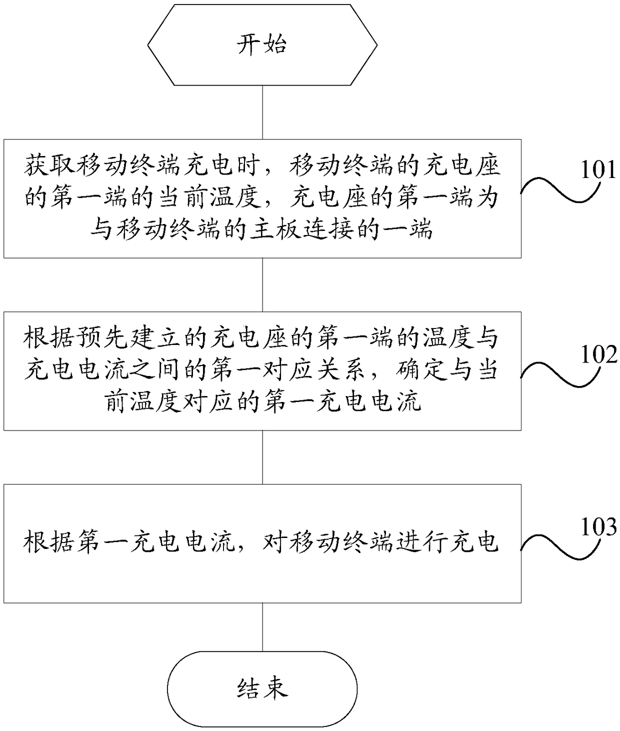
[0026] see figure 1 , the first embodiment of the present invention provides a charging method, comprising:

[0027] Step 101, acquiring the current temperature of the first end of the charging stand of the mobile terminal when the mobile terminal is charging, the first end of the charging stand being the end connected to the main board of the mobile terminal.

[0028] Wherein, the charging stand of the mobile terminal is the charging interface. Usually, the charging stand mainly includes two types of micro USB and Type C. The first end of the charging base is the end connected to the main board of the mobile terminal, that is, the end facing the inside of the mobile terminal. When the mobile terminal is being charged, the first end of the charging stand will generate heat. Therefore, it is necessary to monitor the temperature of the first end of the charging stand.

[0029] Step 102 , according to the pre-established first corresponding relationship between the temperature ...

no. 2 example

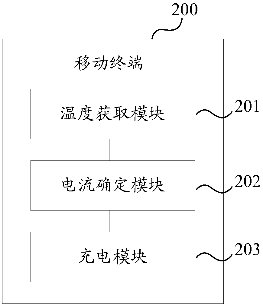
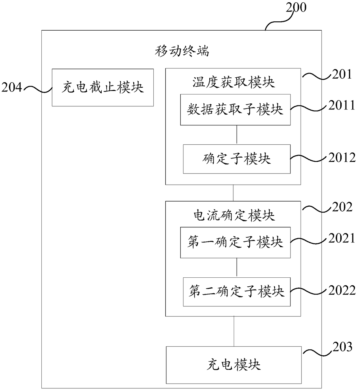
[0050] see figure 2 , figure 2 A block diagram of the mobile terminal 200 provided for the second embodiment of the present invention, figure 2 The mobile terminal 200 shown includes: a temperature acquisition module 201, a current determination module 202 and a charging module 203; and the temperature acquisition module 201 is connected to the current determination module 202, and the current determination module 202 is connected to the charging module 203; wherein,

[0051] The temperature acquisition module 201 is used to acquire the current temperature of the first end of the charging base of the mobile terminal 200 when the mobile terminal 200 is charging, and the first end of the charging base is the end connected to the main board of the mobile terminal 200 .

[0052] Wherein, the charging stand of the mobile terminal 200 is a charging interface. Usually, the charging stand mainly includes two types of microUSB and Type C. The first end of the charging base is the ...

no. 3 example

[0069] Figure 4 is a block diagram of a mobile terminal according to a third embodiment of the present invention. Figure 4 The illustrated mobile terminal 400 includes: at least one processor 401 , a memory 402 , at least one network interface 404 and other user interfaces 403 . Various components in the mobile terminal 400 are coupled together through the bus system 405 . It can be understood that the bus system 405 is used to realize connection and communication between these components. In addition to the data bus, the bus system 405 also includes a power bus, a control bus and a status signal bus. But for clarity, in Figure 4 The various buses are denoted as bus system 405 in FIG.

[0070] Wherein, the user interface 403 may include a display, a keyboard or a pointing device (for example, a mouse, a trackball (trackball), a touch panel or a touch screen, and the like.

[0071] It can be understood that the memory 402 in the embodiment of the present invention may b...


PUM


Abstract

The invention provides a charging method and a mobile terminal. The charging method comprises the steps of obtaining the current temperature of the first end of the charging base of a mobile terminal when the mobile terminal is charged, wherein the first end of the charging base is one end connected with the main board of the mobile terminal; determining a first charging current corresponding to the current temperature based on a pre-built first corresponding relationship between the temperature of the first end of the charging base and a charging current; and charging the mobile terminal based on the first charging current. According to the charging method and the mobile terminal, the problems of relatively slow response and relatively poor flexibility of the existing temperature detecting mode for a charging interface of an electronic device are solved.

Description

technical field [0001] The invention relates to the technical field of electronic equipment, in particular to a charging method and a mobile terminal. Background technique [0002] A charging interface of an electronic device is a main interface for charging, and is one of interfaces commonly used by users. At present, there are mainly two types of charging interfaces: micro USB and Type C. With the rapid progress of mainstream charging technology, the current flowing through the charging interface is also increasing. However, when there is a foreign object in the interface or the deformation of the interface causes the contact resistance to increase, if it is not detected in time, it will still be charged with a large current. If the temperature rises, there may be a risk of burning the fusion shell or the charging interface. Therefore, it is necessary to detect the internal temperature of the interface in time. However, at present, most electronic devices are not set to ...

Claims


Application Information

Patent Timeline
Patent Type & Authority Patents(China)
IPC IPC(8): H02J7/00
CPCH02J7/0088
Inventor 魏华兵肖石文
Owner VIVO MOBILE COMM CO LTD
Why Eureka
Try Eureka