Charger charging circuit, mobile terminal charging circuit, charger and mobile terminal

A charging circuit and mobile terminal technology, applied in battery circuit devices, data exchange chargers, collectors, etc., can solve the problems of poor overcurrent capacity of USB sockets and cables, and achieve the goal of increasing charging speed and charging current Effect

Active Publication Date: 2016-12-14
VIVO MOBILE COMM CO LTD
View PDF2 Cites 9 Cited by
  • Summary
  • Abstract
  • Description
  • Claims
  • Application Information

AI Technical Summary

Problems solved by technology

[0003] Embodiments of the present invention provide a charging circuit for a charger, a charging circuit for a mobile terminal, a charger and a mobile terminal, so as to solve the problem of poor overcurrent capability of standard USB sockets and cables in the prior art

Method used


Image

  • Charger charging circuit, mobile terminal charging circuit, charger and mobile terminal
  • Charger charging circuit, mobile terminal charging circuit, charger and mobile terminal
  • Charger charging circuit, mobile terminal charging circuit, charger and mobile terminal

Examples


no. 1 example

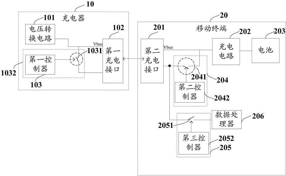
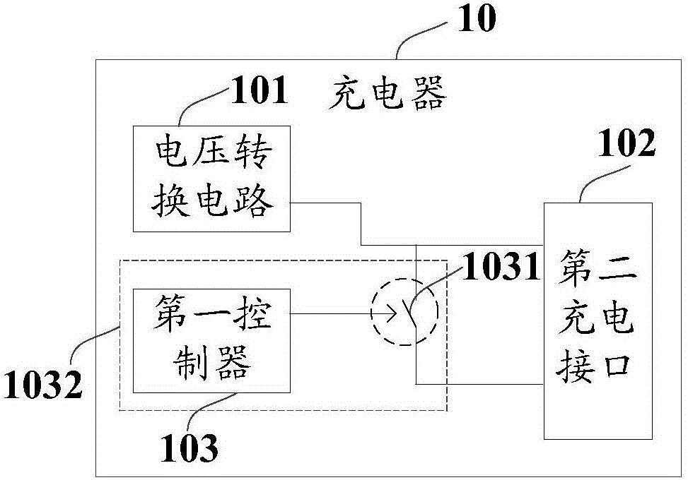
[0033] Such as figure 1 and figure 2 As shown, the embodiment of the present invention provides a charger charging circuit, which is applied to a charger 10 , and the charger 10 specifically includes: a voltage conversion circuit 101 , a first charging interface 102 , and a first control circuit 103 .

[0034] Wherein, the voltage conversion circuit 101 is connected with the AC charging power source, and is mainly used for converting the AC power outputted by the AC charging power source into DC power. Specifically, the voltage conversion circuit 101 may be an AC-DC converter, that is, an AC-DC circuit.

[0035] The first charging interface 102 is used to connect with the second charging interface 201 of the mobile terminal. The first charging interface 102 includes a plurality of terminals or pins, specifically including: a voltage output terminal connected to the voltage conversion circuit 101, and a plurality of The first data transmission end used to transmit data. Whe...

no. 2 example

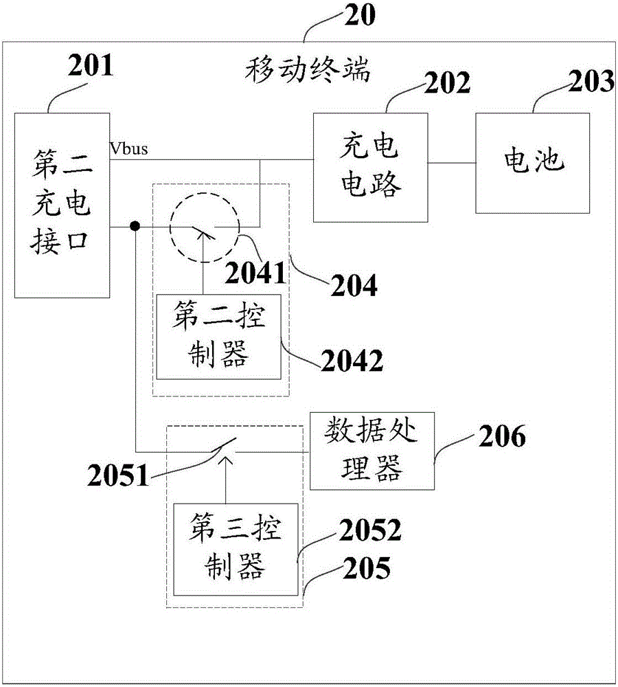
[0044] Such as figure 1 and image 3 As shown, the mobile terminal charging circuit according to the embodiment of the present invention includes: a second charging interface 201 connected to the first charging interface 102 of the charger 10 , a charging control circuit 202 , and a second control circuit 204 .

[0045] Wherein, the second charging interface 201 includes a plurality of terminals or pins, specifically including: a plurality of second data transmission terminals for data transmission, and a voltage input terminal for charging. Wherein, the second charging interface 201 may be a Micro USB interface, or a USB Type-C interface. Wherein, when the second charging interface 201 is a Micro USB interface, the voltage output end of the second charging interface 201 is the voltage pin VBUS pin in the Micro USB interface, and the second data transmission end of the second charging interface 201 includes a Micro USB The data pins D+ pin and D- pin in the interface. When ...


PUM


Abstract

The invention discloses a charger charging circuit, a mobile terminal charging circuit, a charger and a mobile terminal. The charger charging circuit comprises a voltage conversion circuit which converts AC to DC for connecting to an AC charging power supply, a first charging interface, and a first control circuit. The first charging interface is used for connecting to a first charging interface of a mobile terminal; the first charging interface comprises a voltage output terminal connected to a voltage conversion circuit and a plurality of first data transmission terminals; one end of the first control circuit is connected to the voltage conversion circuit, and the other end of the first control circuit is connected to at least one first data transmission terminal among the first data transmission terminals. During fast charging, the first control circuit controls connection between the voltage conversion circuit and the data transmission terminal; current outputted by the voltage conversion circuit flows through paths where the voltage output terminal and the data transmission terminal are arranged, such that the path where the data transmission terminal is arranged can be utilized for charging, which increases charging current and improves charging speed.

Description

technical field [0001] The invention relates to the technical field of intelligent mobile terminals, in particular to a charger charging circuit, a mobile terminal charging circuit, a charger and a mobile terminal. Background technique [0002] With the development and popularization of smart mobile terminals, users have higher and higher requirements for mobile terminals. In addition to requiring mobile terminals to have rich functions, mobile terminals are also required to be able to achieve fast charging and have sufficient battery life. By increasing the charging speed and shortening the user's waiting time for charging, the user experience can be significantly improved. At present, when standard USB sockets and USB cables are used, the maximum current that can be transmitted during charging is restricted by the USB protocol. For example, the maximum transmission current supported by the type-C interface is 5A. When a higher current charging is required, Vbus overcurrent...

Claims


Application Information

Patent Timeline
Patent Type & Authority Applications(China)
IPC IPC(8): H02J7/04
CPCH02J7/045H02J7/04H02J2207/20H02J2207/30H02J7/00714H02J7/00034H02J7/00H02J7/0013H02J7/02
Inventor 贾广琪刘彦彬
Owner VIVO MOBILE COMM CO LTD
Why Eureka
Try Eureka