
Motor cover and motor housing assembly structure

A technology of motor housing and assembly structure, applied in the direction of electromechanical device, housing/cover/support, electrical components, etc., can solve the problems of low installation efficiency, low installation accuracy of motor cover, inconvenient disassembly and assembly, etc. The effect of installation accuracy

Inactive Publication Date: 2016-12-14
WUXI TAICHANG PRECISION MACHINERY CO LTD
View PDF7 Cites 0 Cited by
  • Summary
  • Abstract
  • Description
  • Claims
  • Application Information

AI Technical Summary

Problems solved by technology

[0003] In view of the above problems, the present invention provides an assembly structure of the motor cover and the motor housing, which can solve the problems of low installation accuracy, low installation efficiency, and inconvenient assembly and disassembly of the existing motor cover

Method used


Image

  • Motor cover and motor housing assembly structure
  • Motor cover and motor housing assembly structure
  • Motor cover and motor housing assembly structure

Examples


specific Embodiment approach 1

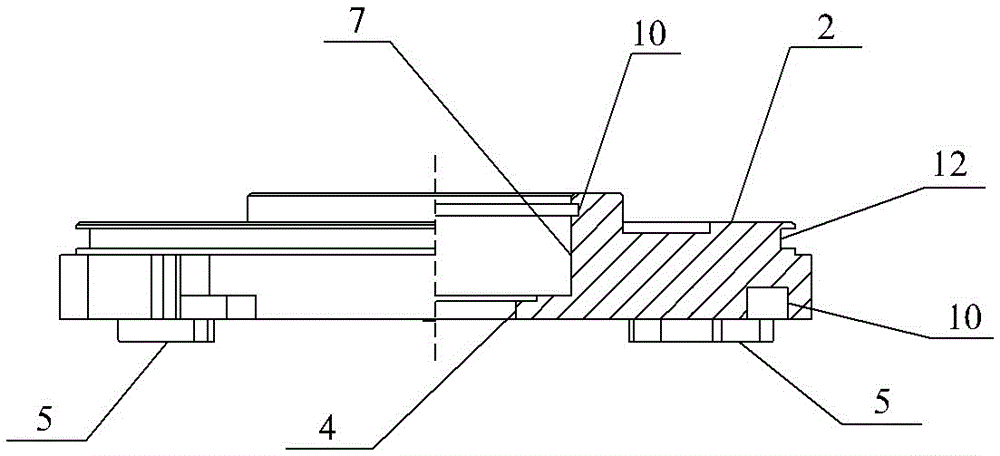
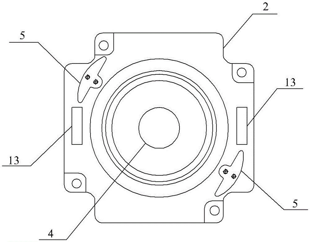
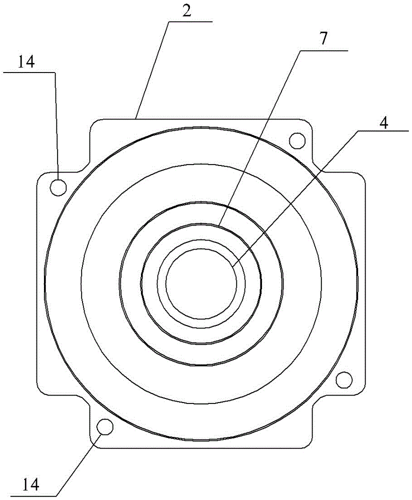
[0017] Specific implementation mode one: combine Figure 1 to Figure 5 Describe this embodiment, an assembly structure of a motor cover and a motor housing in this embodiment, which includes a motor housing 1 and a motor cover 2, and the motor cover 2 is fixed and covered on the motor housing 1 by bolts. There are 3 openings at the end, which are characterized in that: the motor cover 2 is provided with a shaft hole 4 through which the power supply shaft 8 passes, and at least two positioning blocks 5 are fixed on the bottom surface of the motor cover 2, and the positioning blocks 5 are "convex" The positioning blocks 5 are evenly distributed along the circumference of the shaft hole 4, and the convex end of each positioning block 5 points to the center of the shaft hole 4. The motor housing 1 is provided with two positioning blocks 5 facing each other one by one. The positioning groove 6, the positioning block 5 can be embedded in the positioning groove 6, the top surface of ...

specific Embodiment approach 2

[0019] Specific implementation mode two: combination figure 2 Referring to this embodiment, two second grasping grooves 13 are provided on the edge of the bottom surface of the motor cover 2 in this embodiment, and the two second grasping grooves 13 are arranged facing each other. Such design facilitates the grasping of the motor cover 2, and when disassembling, the use of the first grasping groove 12 can make the dismounting and assembling of the motor cover convenient and quick. Other components and connections are the same as those in the first embodiment.

specific Embodiment approach 3

[0020] Specific implementation mode three: combination figure 2 To describe this embodiment, the second grasping groove 13 of this embodiment is a rectangular groove. Other components and connections are the same as those in the second embodiment.


PUM


Abstract

The present invention provides a motor cover and motor housing assembly structure. The problems are solved that the current motor cover is low in installation precision, low in installation efficiency is low and the dismounting is inconvenient. The motor cover of the invention is provided with an axle hole configured to allow the motor shaft to pass through; at least two location blocks are fixedly connected on the bottom of the motor cover; the motor housing is provided with location grooves opposite to two location blocks; the location blocks are embedded in the location grooves; a bearing installation groove having the same axis with the axle hole is arranged on the top surface of the motor cover; the motor shaft is rotatingly connected with the motor cover through a rolling bearing installed in the bearing installation groove; an annular groove is arranged at the side wall of the bearing installation groove side wall located at the upper portion of the rolling bearing along the circumferential direction; an elastic upper cover is sleeved on the motor shaft through the center of the top surface and is in clearance fit with the motor shaft; a flange is arranged at the outer side wall of the lower end of the elastic upper cover along the circumferential direction; the flange is clamped in the annular groove; and a first grabbing groove is arranged at the upper end of the outer side end of the motor cover along the circumferential direction.

Description

technical field [0001] The invention relates to the field of motor assembly, in particular to an assembly structure of a motor cover and a motor housing. Background technique [0002] A motor is a device that converts electrical energy into mechanical energy, and plays an extremely important role in social production and life. When the motor breaks down during use or the inside of the motor needs to be cleaned, the motor cover needs to be removed, and the motor cover is reinstalled after the work is completed. Usually, the motor cover is fixed on the motor casing by bolts, but during the installation process of the motor cover, the screw holes on the motor cover and the screw holes on the motor casing cannot be aligned quickly and accurately, which not only affects the installation accuracy, but also Installation efficiency is low. In addition, the motor cover lacks a structure that is convenient for the operator to grasp, which is inconvenient for the installation and rem...

Claims


Application Information

Patent Timeline
IPC IPC(8): H02K5/04
CPCH02K5/04
Inventor 陈建华
Owner WUXI TAICHANG PRECISION MACHINERY CO LTD
Learn More