
A state-aware software-defined networking method

A software-defined, state-aware technology, applied in electrical components, data exchange networks, remote connection/disconnection of branch offices, etc., can solve problems such as difficulty in multi-path constraints, and achieve high energy efficiency and low energy consumption.

Active Publication Date: 2019-03-15
ANSHAN POWER SUPPLY COMPANY OF STATE GRID LIAONING ELECTRIC POWER COMPANY +3
View PDF4 Cites 0 Cited by
  • Summary
  • Abstract
  • Description
  • Claims
  • Application Information

AI Technical Summary

Problems solved by technology

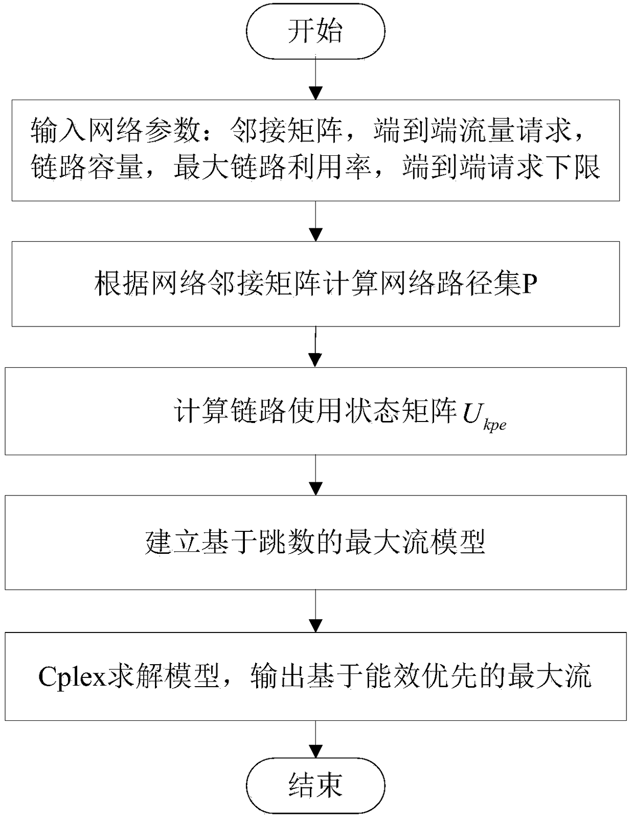
[0006] Aiming at the problem of difficult multi-path constraints in the traditional method, the present invention proposes a state-aware software-defined networking method, which adopts the path-based maximum flow solution, and in order to improve the energy efficiency of the network at the data level, the path hops are limited Conditions, for each end-to-end request to establish a traffic transmission path with the minimum bit energy consumption, to achieve the purpose of energy-efficient data plane network division

Method used


Image

  • A state-aware software-defined networking method
  • A state-aware software-defined networking method
  • A state-aware software-defined networking method

Examples


Embodiment Construction

[0051] The specific embodiment of the present invention will be further described below in conjunction with accompanying drawing:

[0052] A state-aware software-defined networking method described in the present invention includes the following steps:

[0053] Step 1: Input data level network parameters, adjacency matrix A N×N , end-to-end traffic request matrix Γ N×N , link capacity C e , the maximum link utilization α, the lower limit of the traffic request transmission rate β;

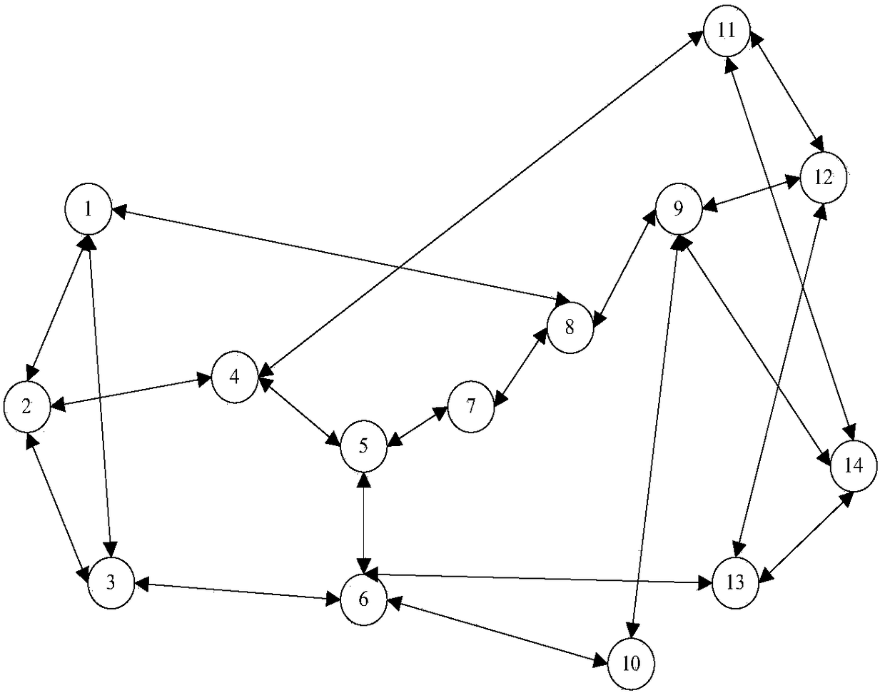
[0054] Given a network G=(V,E), if the directed graph G satisfies: (1) there is exactly one point S with zero in-degree (called the source point); (2) there is exactly one point with zero-out degree D (called sink); (3) Both have a non-negative weight (called link capacity); then G is called a data transmission network, and edge1 v 2 The capacity of > is denoted as A point that is neither a source point nor a sink point is called an intermediate point. If a real-valued function f:E→R is def...


PUM


Abstract

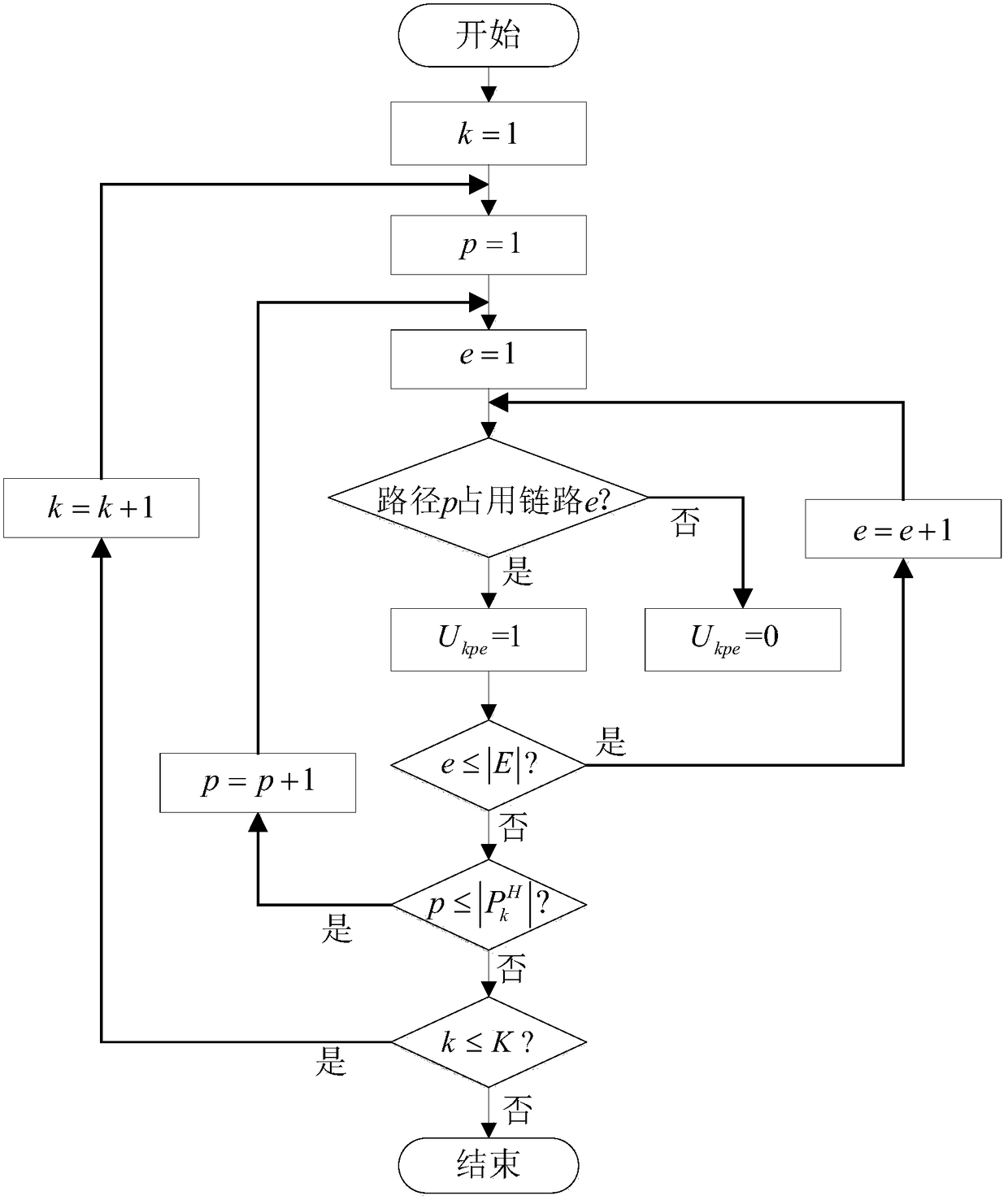
The invention relates to a software definition networking method of state sensing. The software definition networking method comprises steps of: step 1: inputting a data level network parameter, an adjacent matrix AN*N, an end-to-end flow request matrix gammaN*N, link capacity Ce, a maximum link utilization rate alpha and a low request transmission rate lower limit beta; step 2: calculating a data level network path set, and solving all path sets P between two points in a directed connected graph according to a depth-first traversal method of the graph; step 3: calculating a link state matrix Ukpe; step 4: establishing a multi-source multi-sink maximum flow model based on a path hop count; and step 5: solving a model constructed in the step 4 by use of the CPLEX, and outputting the end-to-end maximum flow based on energy efficiency priority. According to the invention, the maximum flow solution based on a path is adopted; in order to improving energy efficiency of a data level network, the path hop count is used as a restriction condition, and a flow transmission path with lowest bit energy consumption is established for an end-to-end request every time, so an objective of division of high energy efficiency data level network is met.

Description

technical field [0001] The invention relates to the key technical field of software-defined optical fiber network, in particular to a state-aware software-defined networking method. Background technique [0002] With the large-scale deployment of virtualization and cloud computing, various broadband data services are developing rapidly, the number of users, bandwidth requirements, and network traffic are constantly increasing, and the energy consumption of network equipment is also increasing steadily. key issues of the network. When the utilization rate of the system server and network is at 15% and the energy and load of the server have a good ratio, the energy consumption of network communication is close to 50% of the total energy consumption. It can be seen that saving the energy consumption of network communication is of great significance to the network system. [0003] At present, there are many studies on network energy efficiency strategies, including traditional...

Claims


Application Information

Patent Timeline
Patent Type & Authority Patents(China)
IPC IPC(8): H04L12/801H04L12/24H04L12/12
CPCH04L12/12H04L41/145H04L47/10
Inventor 易丹孟凡博赵宏昊梁凯张艳萍蒋定德
Owner ANSHAN POWER SUPPLY COMPANY OF STATE GRID LIAONING ELECTRIC POWER COMPANY
Learn More