Fuel delivery device for a saddle tank

A fuel delivery and storage tank technology, applied in mechanical equipment, liquid fuel feeders, layout combined with internal combustion engine fuel supply, etc., can solve the problem of only arranging in one of the saddle chambers, etc.

Inactive Publication Date: 2016-12-14
ROBERT BOSCH GMBH
View PDF7 Cites 0 Cited by
  • Summary
  • Abstract
  • Description
  • Claims
  • Application Information

AI Technical Summary

Problems solved by technology

The problem arises in such saddle tanks that the fuel delivery unit is usually only arranged in one of the saddles and the fuel has to be fed from the second saddle into the first saddle in order to be able to achieve a complete delivery of the fuel
But this is not a preferred solution due to cost

Method used


Image

  • Fuel delivery device for a saddle tank
  • Fuel delivery device for a saddle tank

Examples


Embodiment approach

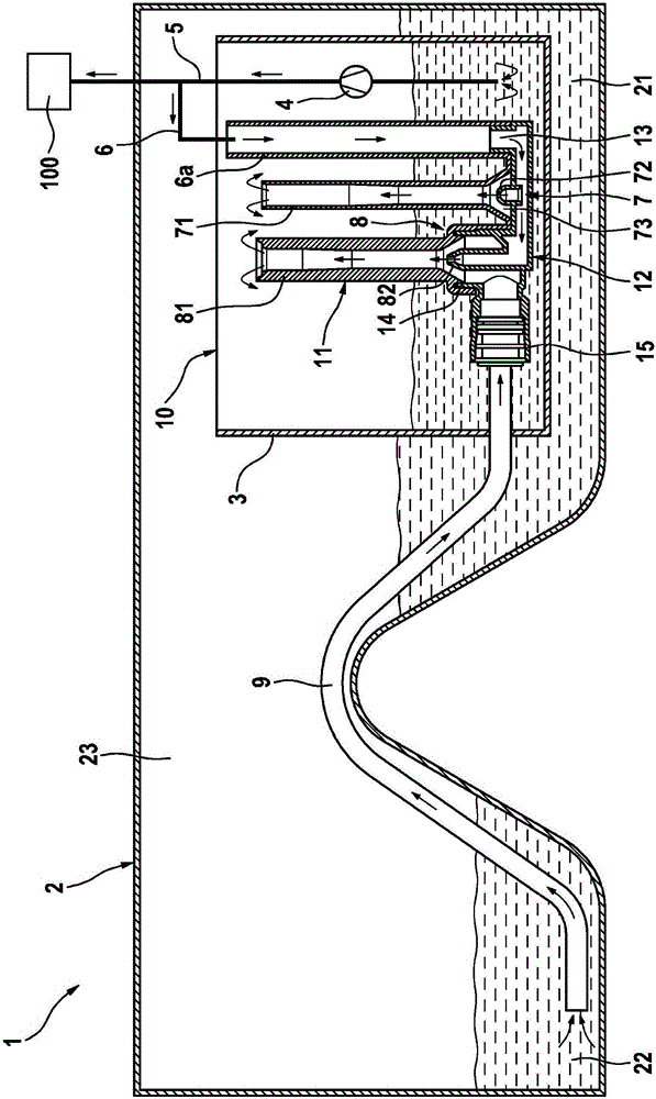
[0017] Next, refer to figure 1 A fuel delivery device 1 according to a first preferred embodiment of the present invention will be described in detail.

[0018] Such as figure 1 As shown schematically, the fuel delivery device 1 is arranged in a saddle tank 2 . The saddle storage tank 2 comprises a first saddle chamber 21 , a second saddle chamber 22 and a bridge connection area 23 connecting the two saddle chambers to each other.

[0019] The fuel delivery system 1 comprises a delivery tank 3 in which a fuel pump 4 and a pre-delivery module for filling the delivery tank 3 are arranged. The pre-delivery module comprises a modular unit 10 with a first module component 11 and a second module component 12, which will be described in detail later.

[0020] A fuel pump 4 delivers fuel from a delivery tank 3 to an internal combustion engine 100 via a fuel delivery line 5 .

[0021] The modular unit 10 comprises two modular components 11 , 12 which are preferably produced by inje...


PUM


Abstract

The invention relates to a fuel delivery device for a saddle tank (2) with a first saddle chamber (21) and a second saddle chamber (22), comprising a delivery pot (3); a fuel pump (4), which is arranged in the delivery pot (3); a drive line (6), which branches off from a fuel delivery line (5); a first suction jet pump (7), which is arranged in the delivery pot (3) and which comprises a first mixing tube (71) and a first nozzle (72), said first suction jet pump (7) being designed to deliver fuel from the first saddle chamber (21) to the delivery pot (3); a second suction jet pump (8) with a second mixing tube (81) and a second nozzle (82), said second suction jet pump (8) being designed to deliver fuel from the second saddle chamber (22) to the delivery pot (3); and a module unit (10) with a first module component (11) and a second module component (12). The first module component (11) comprises the first mixing tube (71) and the second mixing tube (81), and the second module component (12) comprises a feed line connection (13) for the drive line (6), the first nozzle (72) of the first suction jet pump (7), a mixing tube connection (14) for the second mixing tube (81), and a fuel connection (15) for a fuel line (9) from the second saddle chamber. The fuel connection (15) is connected to the mixing tube connection (14) in the second module component (12).

Description

technical field [0001] The present invention relates to a fuel delivery device for a saddle storage tank having first and second saddle regions. Background technique [0002] In the prior art, fuel delivery devices are known in different configurations. For example, document DE 10 2010 061813 A1 shows a fuel delivery device with a suction jet pump, which has a particularly cost-effective and installation-friendly design. In vehicles, however, so-called saddle tanks have recently been used extensively, in which the first and second saddle chambers are connected to one another by means of bridge-shaped, arc-shaped connecting regions. The problem arises in such saddle tanks that the fuel delivery unit is usually only arranged in one of the saddles and the fuel has to be fed from the second saddle into the first saddle in order to be able to achieve a complete delivery of the fuel . Here, it is theoretically possible to arrange a second fuel delivery unit in the second saddle...

Claims


Application Information

Patent Timeline
Patent Type & Authority Applications(China)
IPC IPC(8): F02M37/00B60K15/03F02M37/02F02M37/10
CPCF02M37/0094B60K15/077B60K2015/03111B60K2015/03125B60K2015/03138B60K2015/0325F02M37/0017F02M37/025F02M37/106
Inventor M·拜尔H·P·布劳恩
Owner ROBERT BOSCH GMBH
Why Eureka
Try Eureka